Steel structure and foundation pre-burying connection structure and construction method

A technology for connecting structures and steel structures, which is applied in basic structure engineering, building construction, construction, etc., can solve problems such as voids at the bottom of pre-embedded steel plates, affecting structural force transmission, silting, etc., to speed up construction progress and ensure connection strength , The effect of high installation efficiency

Active Publication Date: 2014-12-24
瑞洲建设集团有限公司
View PDF7 Cites 28 Cited by
  • Summary
  • Abstract
  • Description
  • Claims
  • Application Information

AI Technical Summary

Problems solved by technology

However, in the combined embedded parts, the bottom of the embedded steel plate is prone to problems such as poor concrete pouring, air bubbles in the concrete floating up and depositing on the lower surface of the steel plate, and during the hardening of the concrete and the use of the upper structure, due to the inconsistent deformation of the concrete and the steel plate, problems will occur. The bottom of the pre-embedded steel plate will be hollowed out, which will affect the force transmission effect of the structure and even fail
[0005] To sum up, there are various forms of connection between the steel structure and the foundation. The embedded column base connection structure has the advantages of high rigidity and less steel consumption, but the anti-pull effect is not good, and in the long-term vibration environment, the concrete around the column base is easily damaged. Cracking; Exposed column feet mostly rely on embedded parts, especially combined embedded parts, which can be used for fixing and leveling different forms of steel structure column feet. It is convenient, flexible, efficient, and has high seismic effect, but its Insufficient performance is that the pre-embedded steel plate is not tightly combined with the lower concrete, which affects the structural force transmission

Method used


Image

  • Steel structure and foundation pre-burying connection structure and construction method
  • Steel structure and foundation pre-burying connection structure and construction method
  • Steel structure and foundation pre-burying connection structure and construction method

Examples


Embodiment Construction

[0036] In this embodiment, the concrete mix ratio, technical requirements for pouring construction, technical requirements for steel cutting and welding construction, and technical requirements for steel bar binding and formwork support will not be repeated, and the embodiments of the present invention will be focused on.

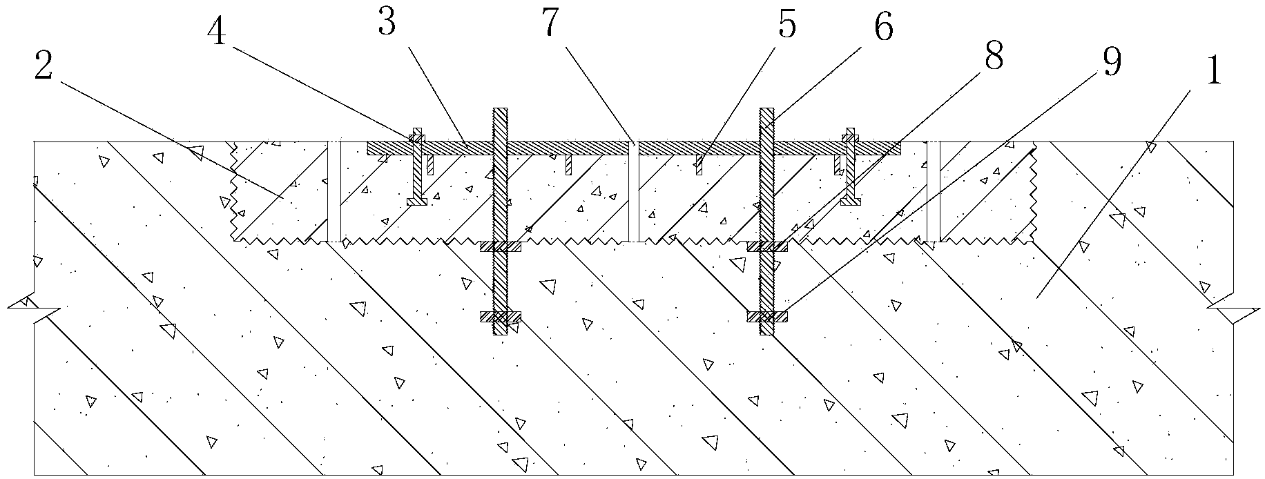
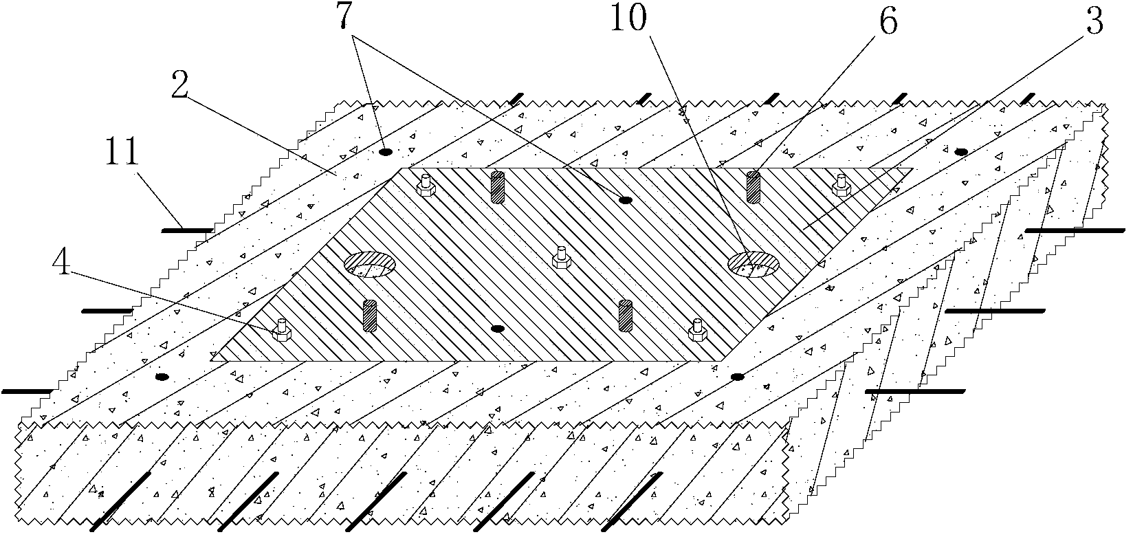
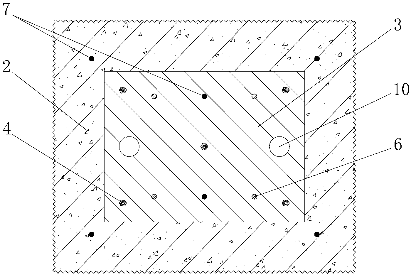
[0037] figure 1 It is a schematic diagram of a steel structure and foundation pre-embedded connection structure of the present invention; figure 2 It is a structural schematic diagram of the prefabricated component of the present invention; image 3 It is a schematic diagram of the upper surface of the prefabricated component of the present invention. refer to Figure 1~3 As shown, a pre-embedded connection structure between steel structure and foundation mainly includes: foundation 1, reinforced concrete connection block 2, connection steel plate 3, prestressed bolt 4, connection short bar 5, connection screw 6 and reserved steel bar 11, etc.

[0038]...


PUM


Abstract

The invention relates to a steel structure and foundation pre-burying connection structure, which is characterized in that the pre-burying connection structure is integrally cast by a prefabricated component and a foundation bottom plate, the prefabricated component is a steel bar concrete connecting block with a connecting steel plate embedded in the upper surface, the periphery of the steel bar concrete connecting block is provided with reserved steel bars connected with steel bars arranged in a foundation, a plurality of steel structure connecting screw rods penetrating through the prefabricated component are arranged in a range of the connecting steel plate, and the lower parts of the connecting screw rods extend into the foundation. The connecting structure provided by the invention has the advantages that the connection intensity of the steel structure and the foundation can be effectively improved, the problems of bottom hollowing and the like due to non-compact casting of the bottom concrete of the traditional pre-burying component and nonuniform deformation of the steel plate and the concrete can be solved, and better technical and economic benefits are realized. The invention also discloses a construction method of the pre-burying connecting structure.

Description

technical field [0001] The invention relates to a steel structure and foundation pre-embedded connection structure and a construction method, in particular to a pre-embedded connection structure in which a prefabricated component is embedded in a foundation floor and a steel structure is indirectly connected to the foundation through connecting bolts on the prefabricated component. It belongs to the field of building installation and is suitable for the connection project between steel structure and concrete foundation, especially for the structural project of long-term vibration during the use of the upper steel structure. Background technique [0002] Because steel structure buildings have many advantages such as light weight, high strength, good plastic toughness, fast construction speed, beautiful appearance, etc., especially their reliable force transmission performance, they have been more and more widely used in building structure design in recent years. The bearing c...

Claims


Application Information

Patent Timeline
Patent Type & Authority Applications(China)
IPC IPC(8): E02D27/42E04B1/41
Inventor 孙健高利阳孙涛蒋高庆张文王立波刘强孙夫艳裴中月周桂宇
Owner 瑞洲建设集团有限公司
Why Eureka
Try Eureka