Force arm actuated power generating device

A technology of power generation device and lever arm, which is applied in the field of lever arm actuated power generation device, can solve problems such as the inability to maximize energy conversion, and achieve the effects of short investment recovery period, low cost and small footprint

Inactive Publication Date: 2014-12-24
管群祥
View PDF5 Cites 0 Cited by
  • Summary
  • Abstract
  • Description
  • Claims
  • Application Information

AI Technical Summary

Problems solved by technology

However, the force acting near the center of the drive wheel and the force near the edge of the drive wheel perform work on the drive wheel with completely different efficiencies, resulting in failure to maximize energy conversion

Method used


Image

  • Force arm actuated power generating device
  • Force arm actuated power generating device
  • Force arm actuated power generating device

Examples


Embodiment Construction

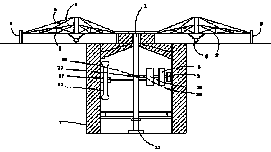
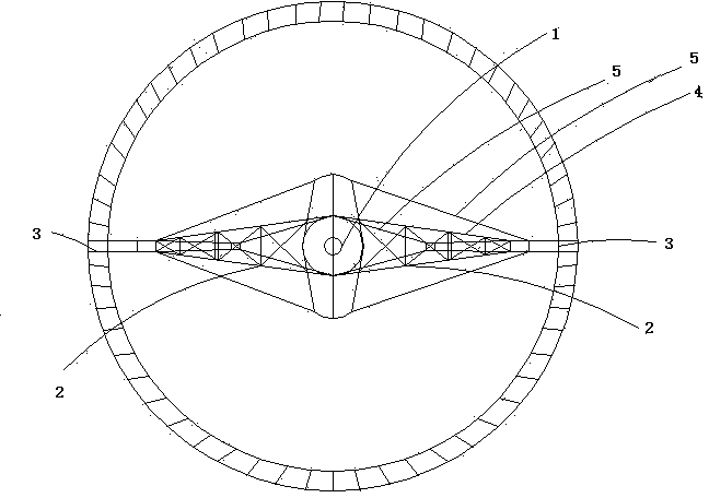
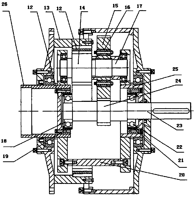
[0011] Such as Figure 1-3 As shown, the force arm actuated power generation device includes a first transmission shaft 1, a force arm 2, a driving source 3, a steel frame 4, a steel cable 5, a pulley 6, a support frame 7, a power generator Speed ​​box 8, a generator 9, a flywheel 10, a base 11, an inner ring gear 12, a speed-increasing box body 13, a small planetary gear 14, a large planetary gear 15, a set of body 16, a planet Gear shaft 17, a front bearing 18, a front elastic sleeve 19, a planet carrier 20, a rear elastic sleeve 21, a rear bearing 22, a central shaft 23, a sun gear 24, a rear bearing support sleeve 25, a first Two transmission shafts 26, a flywheel transmission shaft 27, a longitudinal bevel gear 28, a transverse bevel gear 29, a flywheel speed increasing box 30.

[0012] combine Figure 1-3 As shown, in this embodiment, the drive source 3 is detachably connected to the arm 2 in the tram mode to provide initial power for the arm 2, but the drive source 3 ...


PUM

PropertyMeasurementUnit
Radius lengthaaaaaaaaaa

Abstract

The invention relates to a force arm actuated power generating device. The force arm actuated power generating device comprises a force arm, a first transmission shaft, a power generating speed-increasing box, a second transmission shaft, a power generator, two drive sources, a flywheel, a flywheel speed-increasing box and a flywheel transmission shaft, wherein the first transmission shaft is vertically fixed to the center of the force arm; the first transmission shaft is in engaged connection with the second transmission shaft; the second transmission shaft is in detachable connection with an input end of the power generating speed-increasing box through the flywheel speed-increasing box; the two drive sources act at the two ends of the force arm, and are used for driving the force arm to rotate. According to the force arm actuated power generating device provided by the invention, the drive sources only act at the end parts of the force arm, so that the energy output from the drive sources can be transmitted to the power generator maximally, and the maximization of energy conversion is realized.

Description

[0001] technical field [0002] The invention relates to a power generating device, in particular to a force arm actuated power generating device. Background technique [0003] A traditional hydroelectric generator or a wind generator includes a driving wheel, and in the process of driving the driving wheel to rotate by water or wind, the water or wind directly acts on each point of the blade of the driving wheel . However, the force acting near the center of the driving wheel and the force acting near the edge of the driving wheel perform work on the driving wheel with completely different efficiencies, resulting in failure to maximize energy conversion. Contents of the invention [0004] In view of this, it is necessary to provide an arm actuated power generation device capable of maximizing energy conversion. [0005] A force arm actuated power generation device, comprising a force arm, a first transmission shaft, a power generation speed-up box, a second power t...

Claims


Application Information

Patent Timeline
IPC IPC(8): F03G7/00F03D9/00F03B13/00
CPCY02E10/72Y02P70/50
Inventor 管群祥
Owner 管群祥
Why Eureka
Try Eureka