
Cotton flow sensor

A flow sensor and cotton technology, applied in the field of flow sensors, can solve the problems that affect the flexibility of the cotton box load, affect the accuracy of data, and reduce the accuracy of production measurement, etc., and achieve strong anti-electromagnetic interference ability, low cost, Improved stability and accuracy effects

Inactive Publication Date: 2014-12-24
SHANGHAI UNIV
View PDF6 Cites 0 Cited by
  • Summary
  • Abstract
  • Description
  • Claims
  • Application Information

AI Technical Summary

Problems solved by technology

There are mainly three types of flow sensors used in cotton measurement in my country: one is direct measurement, which is directly measured through the measuring container suspended in the cotton box. Although this method is simple, it affects the loading capacity of the cotton box and the flexibility of the cotton picker; The cotton output is measured by the sound of the seed cotton flowing through the cotton pipe to the cotton box. This method is susceptible to external interference during the operation of the cotton picker, which affects the accuracy of the data; the third is to purchase finished sensors from foreign companies. It is expensive to measure, and generally only a pair of sensors are installed on the cotton pipeline, and the single measurement direction reduces the accuracy of its production measurement

Method used


Image

  • Cotton flow sensor
  • Cotton flow sensor
  • Cotton flow sensor

Examples


Embodiment 1

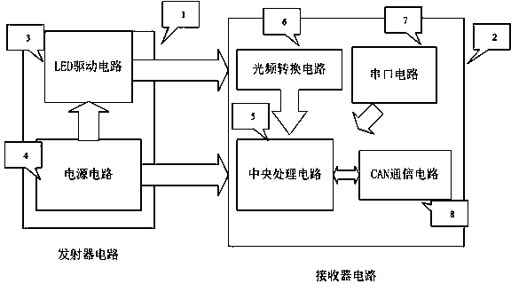
[0024] see figure 1 , the cotton flow sensor includes a transmitter circuit (1) and a receiver circuit (2). It is characterized in that: the transmitter circuit (1) is composed of a power supply circuit (4) connected to an LED drive circuit (3); the receiver circuit (2) is composed of a central processing circuit (5) connected to an optical frequency converter circuit (6), a serial port circuit (7) and a CAN communication circuit (8); the power supply circuit (4) is also connected to the LED drive circuit (3), the central processing circuit (5), the optical frequency conversion circuit (6), The serial port circuit (7), the CAN communication circuit (8); the LED drive circuit (3) is connected to the optical frequency conversion circuit (6).

Embodiment 2

[0025] Embodiment two: the present embodiment is basically the same as embodiment one, and the features are as follows:

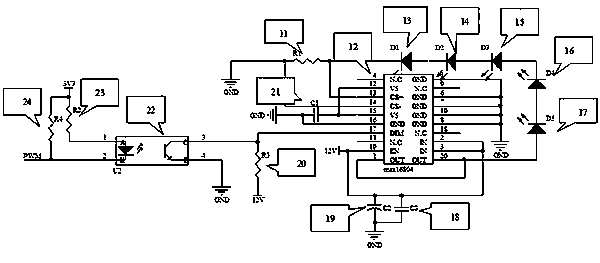
[0026] figure 2 Shows the LED drive circuit in the transmitter circuit (1): the central processing circuit (5) sends a PWM signal to the transmitter circuit, and the signal is connected to a resistor R4 (24) to a 3.3V voltage, and at the same time, the signal is connected to a photoelectric isolation The chip (22) has 2 pins, the 1 pin of the photoelectric isolation chip (22) is connected to a resistor R2 (23) to connect to 3.3V voltage, the 4 pin is connected to ground, and the 3 pin is connected to a resistor R3 (20) to connect to 12V voltage At the same time, this pin is connected to the 17th pin of a voltage regulation chip MAX16804 (12), and the 1st pin of the voltage regulation chip MAX16804 (12) is connected to the 20th pin to connect to the positive pole of the light-emitting diode D5 (17), and the negative pole of the light-emitting diode D5 (17) ...


PUM


Abstract

The invention discloses a cotton flow sensor. The sensor mainly consists of a transmitter and a receiver, wherein a transmitter circuit comprises an LED (Light Emitting Diode) drive circuit and a power supply circuit; a receiver circuit comprises a light frequency conversion circuit, a central processing circuit, a CAN (Control Area Network) communication circuit and a serial port circuit. When cotton passes through a cotton conveying pipeline, the intensity of light, transmitted from the transmitter, received by the receiver can be weakened; the flow of mass instantaneously passing through the cotton conveying pipeline can be indirectly measured through measuring the intensity of the received light; in a receiving circuit of a receiving terminal, a light frequency conversion chip, which plays a key role, can convert light intensity signals into electrical signals, and the output electrical signals are calculated by the central processing circuit, thereby obtaining a final measured value.

Description

technical field [0001] The invention relates to a flow sensor, in particular to a cotton flow sensor based on an optical principle. The non-contact flow sensor is used to measure the instantaneous mass flow of cotton passing through a cotton delivery pipeline of a cotton picker in real time. Background technique [0002] The cotton flow sensor is a device developed by developed countries in the 1990s and used in precision agricultural research. The flow sensor is the core component of the entire yield detection system, its stability and accuracy directly determine the accuracy of the cotton field yield, and at the same time affect the accuracy of the entire yield detection system. There are mainly three types of flow sensors used in cotton measurement in my country: one is direct measurement, which is directly measured through the measuring container suspended in the cotton box. Although this method is simple, it affects the loading capacity of the cotton box and the f...

Claims


Application Information

Patent Timeline
Patent Type & Authority Applications(China)
IPC IPC(8): G01F1/86
Inventor 李闯苗中华沈一筹胡晓东周广兴王胜军
Owner SHANGHAI UNIV
Learn More