Monitoring method for creep deformation design of high-temperature part of thermal power generating unit

A technology for thermal power generating units and high-temperature components, which is applied in computing, electrical digital data processing, special data processing applications, etc., and can solve problems such as creep damage of high-temperature components of thermal power generating units

Active Publication Date: 2014-12-24
SHANGHAI POWER EQUIP RES INST
View PDF4 Cites 2 Cited by
  • Summary
  • Abstract
  • Description
  • Claims
  • Application Information

AI Technical Summary

Problems solved by technology

If the design and monitoring of creep deformation is improper, it will lead to creep damage of high-temperature components of thermal power generation units during operation, and engineering is in urgent need of a design monitoring method and system for creep deformation of high-temperature components of thermal power generation units
The applicant has applied for a patent "A Method and System for Predicting the Creep Life of High-temperature Components of Steam Turbine" with the application number of 200710039899.8, which quantitatively predicts the remaining creep life of high-temperature components of steam turbines during the use stage; "Analysis of the High-temperature Creep Strength of the High-Pressure Rotor of a 660MW Ultra-supercritical Steam Turbine" published in the "Jiang Puning" paper "Analysis of the Creep Strength of the High-pressure Outer Cylinder of a 1000MW Ultra-supercritical Steam Turbine" in the "Journal of Power Engineering" No. 1, 2013 The paper "Analysis of Creep Strength of Ultra-Supercritical Unit High Pressure Inner Cylinder" published by Yu Chao and Yu Chao in the 5th issue of "Journal of Power Engineering" in 2014, as well as the creep strength analysis of thermal power generation units reported in public literature, are all about thermal power generation. The creep strength of the high-temperature components of the unit has been calculated and analyzed, but there is no suitable method and system available for the design and monitoring of the creep deformation of the high-temperature components of the thermal power generation unit

Method used


Image

  • Monitoring method for creep deformation design of high-temperature part of thermal power generating unit
  • Monitoring method for creep deformation design of high-temperature part of thermal power generating unit
  • Monitoring method for creep deformation design of high-temperature part of thermal power generating unit

Examples


Embodiment

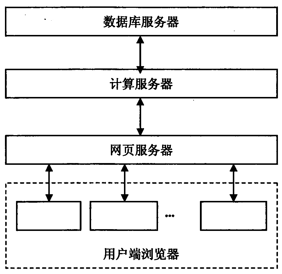
[0048] Such as figure 1 As shown, it is a block diagram of the design monitoring system for the creep deformation of the high-temperature parts of the power generating set adopted in the present invention, and the creep deformation design monitoring system of the high-temperature parts of the thermal power generating set is composed of a creep deformation online computing server and a database server , web server and client browser, the computing server is connected to the database server and the web server, the web server is connected to the client browser, and the database server stores the physical performance data of the high-temperature components of the power generation unit, including the material creep test constant n Wait.

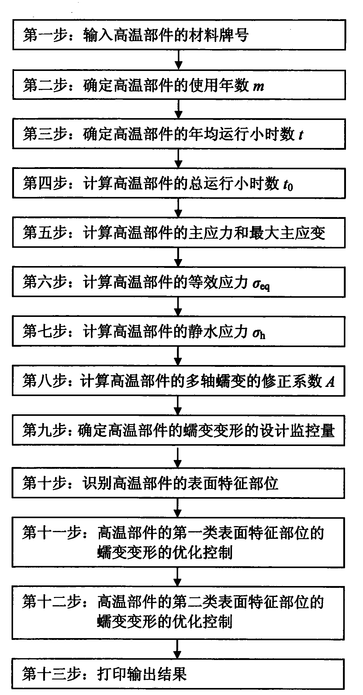
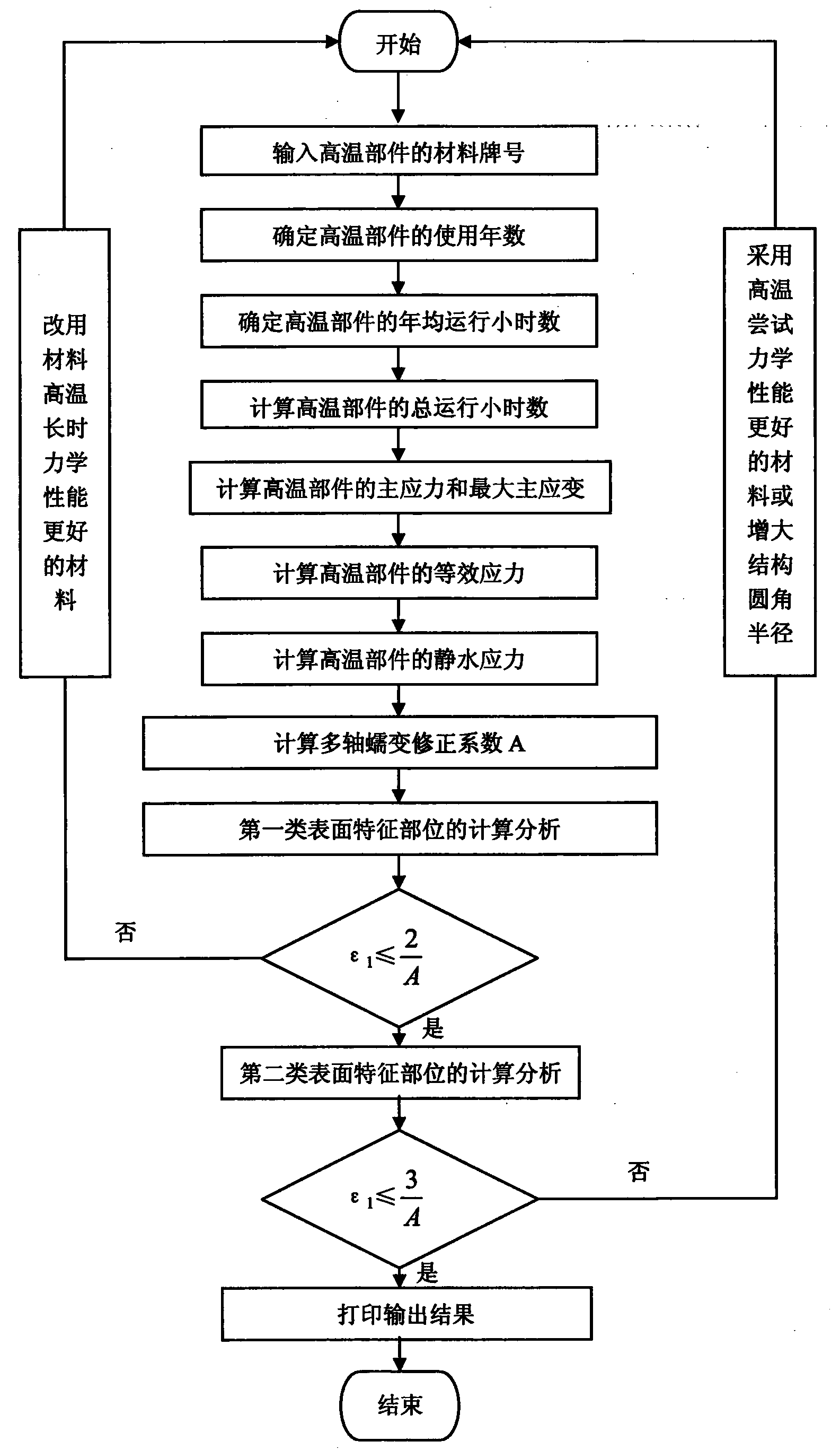
[0049] Such as figure 2 Shown, is the flowchart of the method adopted in the present invention, as image 3 As shown, it is a block diagram of the computer software adopted by the creep deformation calculation server of the present invention, t...


PUM


Abstract

The invention provides a monitoring method for creep deformation design of a high-temperature part of a thermal power generating unit. The monitoring method specifically comprises the following steps: inputting a material mark of the high-temperature part; determining service years m of the high-temperature part; determining annual average running hours t of the high-temperature part; calculating total running hours t0 of the high-temperature part; calculating principal stress and maximum principal strain of the high-temperature part; calculating equivalent stress sigma<eq> of the high-temperature part; calculating hydrostatic stress sigma<h> of the high-temperature part; calculating a correction factor A of multi-axial creep of the high-temperature part; determining design monitoring amounts of creep deformation of the high-temperature part; recognizing surface characteristic parts of the high-temperature part; conducting optimization control of creep deformation of a first class of surface characteristic parts; conducting optimization control of creep deformation of a second class of surface characteristic parts; printing output results. The monitoring method for the creep deformation design of the high-temperature part of the thermal power generating unit realizes quantitative prediction and design monitoring of the creep deformation of the high-temperature part of the thermal power generating unit.

Description

technical field [0001] The invention relates to a design monitoring method for creep deformation of high-temperature components of a thermal power generating set, and belongs to the technical field of thermal generating sets. Background technique [0002] The high-temperature components of the thermal power generation unit with creep damage as the main failure mode include: ultra-high pressure rotor, high-pressure rotor, medium-pressure rotor, ultra-high pressure inner cylinder, high-pressure inner cylinder, medium-pressure inner cylinder, ultra-high pressure outer cylinder, high-pressure outer cylinder , medium pressure outer cylinder, super high pressure main steam valve casing, high pressure main steam valve casing, medium pressure main steam valve casing, super high pressure regulating valve casing, high pressure regulating valve casing, medium pressure regulating valve casing, super high pressure steam chamber, high pressure steam chamber, medium pressure steam chamber,...

Claims


Application Information

Patent Timeline
Patent Type & Authority Applications(China)
IPC IPC(8): G06F19/00G06F17/50
CPCY02E60/00
Inventor 史进渊邓志成汪勇杨宇郝宁
Owner SHANGHAI POWER EQUIP RES INST
Why Eureka
Try Eureka