Combined waveguide

A technology of waveguide and waveguide port, which is applied in the field of communication to achieve the effects of improving loss, improving insertion loss and improving transmission efficiency

Active Publication Date: 2014-12-24
HUAWEI TECH CO LTD
View PDF2 Cites 21 Cited by
  • Summary
  • Abstract
  • Description
  • Claims
  • Application Information

AI Technical Summary

Problems solved by technology

[0012] An embodiment of the present invention provides a combined waveguide to solve the problem of switching between a gap waveguide and a rectangular waveguide or a microstrip line in the prior art

Method used


Image

  • Combined waveguide
  • Combined waveguide
  • Combined waveguide

Examples


Embodiment 1

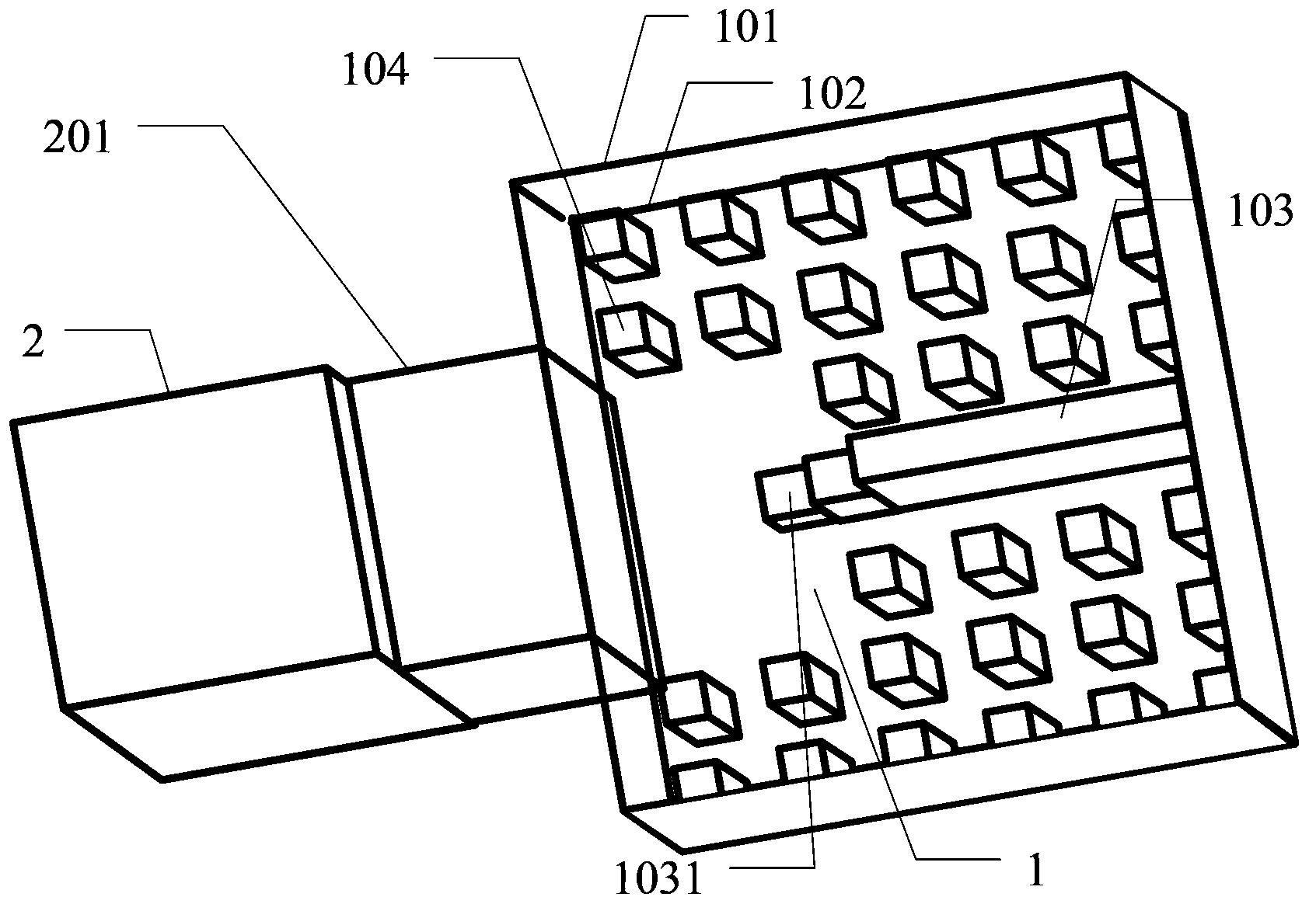
[0060] image 3 It is a three-dimensional schematic diagram of a horizontal transition structure between a gap waveguide and a rectangular waveguide according to an embodiment of the present invention, Figure 4 It is a schematic diagram of the right side view of the transition structure of the rectangular waveguide described in the embodiment of the present invention, Figure 5 It is a schematic front view of the horizontal transition structure between the gap waveguide and the rectangular waveguide according to the embodiment of the present invention, Figure 6 It is a schematic top view of the horizontal transition structure between the gap waveguide and the rectangular waveguide according to the embodiment of the present invention, as shown in Figure 3 to Figure 6 As shown, in the combined waveguide described in Embodiment 1 of the present invention, the horizontal transfer structure of the gap waveguide and the rectangular waveguide specifically includes:

[0061] The ...

Embodiment 2

[0071] Figure 8 It is a three-dimensional schematic diagram of a vertical transition structure between a gap waveguide and a rectangular waveguide according to an embodiment of the present invention, Figure 9 It is a schematic diagram of the right side view of the vertical transition structure between the gap waveguide and the rectangular waveguide according to the embodiment of the present invention, Figure 10 It is a schematic top view of the vertical transition structure between the gap waveguide and the rectangular waveguide according to the embodiment of the present invention, as shown in Figure 8 to Figure 10 As shown, in the combined waveguide described in Embodiment 2 of the present invention, the vertical transfer structure of the gap waveguide and the rectangular waveguide specifically includes:

[0072] The upper plate 101 of the air gap waveguide has a rectangular opening 1011, one side of the rectangular opening 1011 is perpendicular to the ridge 103 of the a...

Embodiment 3

[0082] Figure 11 It is a three-dimensional schematic diagram of the horizontal transfer structure between the gap waveguide and the microstrip line according to the embodiment of the present invention, Figure 12 It is a schematic top view of the gap waveguide and the microstrip line horizontal transition structure according to the embodiment of the present invention, Figure 13 It is a schematic front view of the gap waveguide and the microstrip line horizontal transfer structure of the embodiment of the present invention, as shown in Figure 11 to Figure 13 As shown, in the combined waveguide described in Embodiment 3 of the present invention, the structure of the horizontal transfer between the gap waveguide and the microstrip line specifically includes:

[0083] The upper plate 101 of the air gap waveguide is connected to the floor 301 of the microstrip line or the upper plate 101 of the air gap waveguide and the floor 301 of the microstrip line are all arranged on the s...


PUM


Abstract

The invention discloses a combined waveguide. The combined waveguide is formed by a gap waveguide and a rectangular waveguide in a horizontal or vertical transferring mode, or the combined waveguide is formed by a gap waveguide and a micro-strip line in a horizontal transferring mode. According to the combined waveguide, the effect of connecting and matching of the gap waveguide and the rectangular waveguide or the micro-strip line in the transferring process is achieved, and the gap waveguide can be applied to an existing high-frequency circuit structure; in comparison with the mode of adopting a traditional transmitting line, the loss of a system can be reduced, the transmitting efficiency is improved, the processing difficulty of a circuit is lowered, the processing cost is reduced, and the insertion loss of the system is reduced.

Description

technical field [0001] The invention relates to the technical field of communication, in particular to a combined waveguide. Background technique [0002] Electronic devices are now widely used for the transmission of various signals, which are divided into high-frequency signals and low-frequency signals. For the transmission carriers of these signals, low-frequency signals are usually transmitted in the form of wires and cables, and high-frequency signals are mainly transmitted in the form of radio waves. For high-frequency signals, the transmission hardware includes both high-frequency transmission lines and low-frequency transmission lines. High-frequency transmission lines are used to transmit and receive radio waves, and low-frequency transmission lines are used to transmit sound or video information that needs to be modulated. Traditional high frequency transmission lines include: rectangular waveguide, microstrip line. [0003] With the development of communication...

Claims


Application Information

Patent Timeline
Patent Type & Authority Applications(China)
IPC IPC(8): H01P5/08H01P5/107
Inventor 邹克利郭智力陈静涛
Owner HUAWEI TECH CO LTD
Why Eureka
Try Eureka