Optical fiber fusion connector and method

An optical fiber fusion and connector technology, applied in the field of optical fibers, can solve the problems of difficult optical fiber fusion coupling, high power density, laser damage, etc., and achieve the effect of improving the end face damage threshold, efficient fusion, and reducing the end face reflectivity.

Active Publication Date: 2019-07-23
SHANGHAI INST OF OPTICS & FINE MECHANICS CHINESE ACAD OF SCI
View PDF24 Cites 0 Cited by
  • Summary
  • Abstract
  • Description
  • Claims
  • Application Information

AI Technical Summary

Problems solved by technology

[0004] However, when the hollow-core fiber is used as the remote flexible transmission link of the fiber laser system, it is inevitable to fuse the hollow-core fiber with the solid-core fiber in the fiber laser, which is limited to the structural difference between the solid-core fiber and the hollow-core fiber , which often leads to difficulties in the fusion splice coupling of the two fibers
Specifically, since the power of current fiber lasers is generally high (for example, the power of commercial fiber lasers has exceeded 10,000 watts), and the core diameter of the commonly used double-clad fibers is generally only tens of microns, which makes the fiber core The transmitted power density is very high, so if the laser output end face directly faces the hollow core, it will be very easy to damage, and at the same time, the reflected light from the end face will also damage the laser; in addition, there are air hole collapse and mode Field matching issues need to be considered

Method used


Image

  • Optical fiber fusion connector and method
  • Optical fiber fusion connector and method
  • Optical fiber fusion connector and method

Examples


Embodiment 1

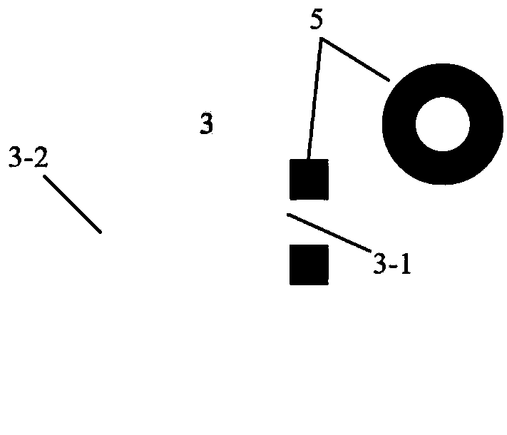
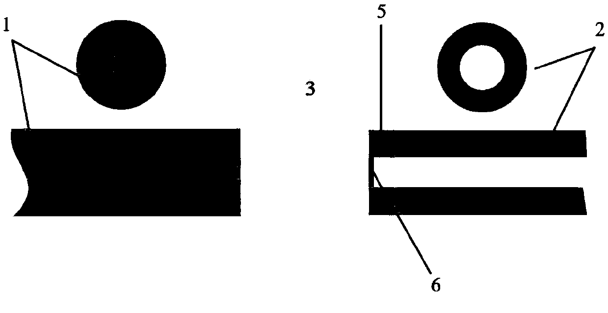
[0039] Example 1: Please refer to Figure 4 , Figure 4 It is a schematic diagram of the fusion splicing of a double-clad solid-core fiber and a nodeless anti-resonant hollow-core fiber: fiber 1 at the laser input end is a double-clad fiber, fiber 2 at the laser output end is a node-free anti-resonant hollow-core fiber, and the transition ring 5 is quartz ring.

[0040] 1) Obtain a double-clad fiber with a core diameter of 30 μm to be fused and a nodeless anti-resonant hollow fiber with a core diameter of 70 μm and a bare fiber diameter of 260 μm, strip the coating layer of the two, and then use a fiber cutter Cutting to ensure the smoothness and cleanliness of the fiber end face.

[0041] 2) The double-clad fiber is fused with the laser input end face 3-2 of the fiber end cap 3, so that the high-power laser beam in the core of the double-clad fiber is expanded 4, and the beam output diameter is diffused from about 30 μm to 60 μm -65μm, reduce the laser power density, and i...

Embodiment 2

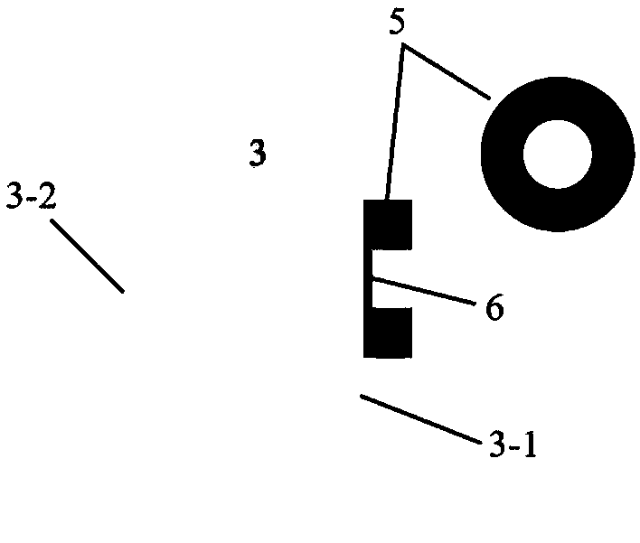
[0045] Example 2: Please refer to Figure 5 , Figure 5 Schematic diagram of fusion splicing of double-clad solid-core fiber and ice-cream anti-resonance hollow-core fiber: fiber 1 at the laser input end is double-clad fiber, fiber 2 at the laser output end is ice-cream anti-resonance hollow-core fiber, and transition ring 5 is quartz ring.

[0046] 1) Obtain the double-clad optical fiber with a core diameter of 10 μm and the ice-cream anti-resonant hollow-core optical fiber with a core diameter of 36 μm and a bare fiber diameter of 130 μm to be fused, strip the coating layer of the two, and then use a fiber cutter Cutting to ensure the smoothness and cleanliness of the fiber end face.

[0047] 2) The output end face of the double-clad fiber is fused with the fiber end cap 3 to expand the high-power laser beam in the core of the double-clad fiber. As shown in 4, the output diameter of the beam is diffused from about 10 μm to 30 μm Left and right, the laser power density is ...


PUM


Abstract

The invention discloses an optical fiber fusion connector and method. The optical fiber fusion connector includes an optical fiber end cap and a transition ring, which can realize the fusion of different types of optical fibers, especially for the fusion of a solid core optical fiber and a hollow-core optical fiber which are used for high-power laser transmission. The optical fiber end cap technology is used for performing beam expanding on the laser, so as to reduce the power density of the output end face; then a transition ring is introduced at the laser output end face of the end cap, so as to perform antireflection film treatment on the laser output end face of the end cap; and then the transition ring and the hollow-core optical fiber are fused. The invention can realize efficient fusion between the hollow-core optical fiber and the solid core optical fiber, and solves the problem of connection matching between the hollow-core optical fiber and the optical fiber laser system in the prior art, especially the high-power optical fiber laser system, which is convenient for remote flexible transmission of the laser.

Description

technical field [0001] The invention relates to the technical field of optical fibers, in particular to an optical fiber and an optical fiber fusion splicing connector and method. Background technique [0002] In recent years, fiber lasers have been widely used in industrial, medical, scientific research, military and other fields due to their advantages of high power, high reliability, and high beam quality. However, with the gradual increase in the output power of fiber lasers, nonlinear effects such as stimulated Raman scattering, stimulated Brillouin scattering, and self-phase modulation caused by the interaction between laser and dielectric materials, as well as thermal damage restrict the development of fiber lasers. Also more obvious. In terms of application, the restrictive effect is mainly manifested in the difficulty of finding a suitable medium for long-distance transmission of high-power lasers, because ordinary transmission fibers are affected by nonlinear effe...

Claims


Application Information

Patent Timeline
Patent Type & Authority Applications(China)
IPC IPC(8): G02B6/255G02B6/245G02B6/25
CPCG02B6/245G02B6/25G02B6/2551
Inventor 吴达坤刘垠垚李夏廖梅松
Owner SHANGHAI INST OF OPTICS & FINE MECHANICS CHINESE ACAD OF SCI
Why Eureka
Try Eureka