General engine spark plug cap

A general-purpose engine, spark plug cap technology, applied to spark plugs, electrical components, circuits, etc., can solve the problems of difficult cleaning of residues, complex assembly process, poor continuity between branch springs and resistors, etc., to eliminate non-conduction phenomenon. , The assembly process is simple, and the effect of improving the conduction performance

Inactive Publication Date: 2014-12-24
CHONGQING CONGREN ELECTROMECHANICAL
View PDF6 Cites 1 Cited by
  • Summary
  • Abstract
  • Description
  • Claims
  • Application Information

AI Technical Summary

Problems solved by technology

[0003] 1) The conductive cap is fixed in the main tube of the main body by interference fit, which is inconvenient to disassemble and assemble, and the assembly efficiency is low;
[0004] 2) The screw has a round head structure, which must be assembled at a high temperature in a hot state (about 150°C). After cooling, the screw can not rotate in the branch pipe; not only that, but the assembly of other parts is also carried out in a hot state. On the one hand, the assembly The process is complicated, the assembly operation is inconvenient, and the operator is easy to burn his hands; on the other hand, the residue in the body is not easy to clean up, which may easily cause poor conduction of the product;
[0005] 3) One end of the resistor is in contact with the branch spring, and the other end is in contact with the screw. The contact performance between the end surface of the resistor and the screw is not good, and there may be no conduction; at the same time, the contact surface between the resistor and the branch spring is small, and the positioning of the branch spring is limited. Poor reliability, prone to skewing, resulting in poor continuity between branch spring and resistor

Method used


Image

  • General engine spark plug cap
  • General engine spark plug cap

Examples


Embodiment Construction

[0016] Below in conjunction with accompanying drawing and embodiment the present invention will be further described:

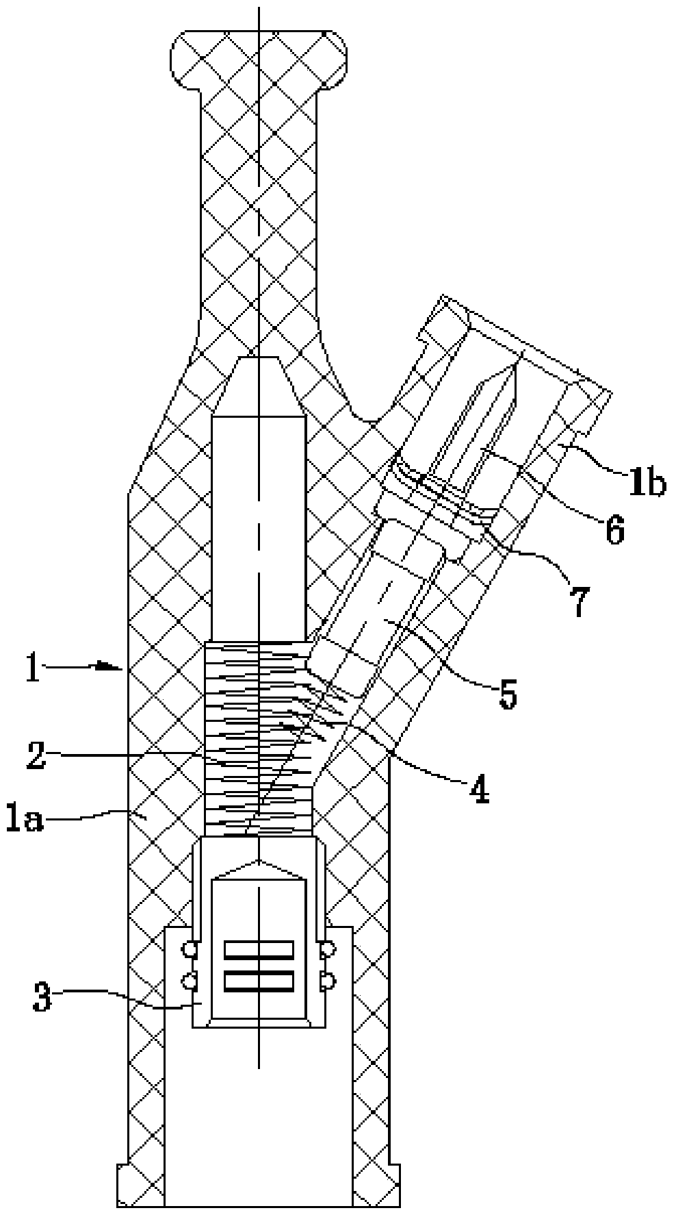
[0017] Such as figure 1 As shown, the main body 1 is formed by injection molding, and is composed of a main pipe 1a and a branch pipe 1b. The body of the main pipe 1a extends obliquely to form a branch pipe 1b, and the angle between the branch pipe 1b and the main pipe 1a is 30°. A main pipe spring 2 and a conductive cap 3 are installed in the main pipe 1a, wherein the inner end of the main pipe spring 2 abuts against the stepped surface in the main pipe 1a, the outer end of the main pipe spring 2 abuts against the conductive cap 3, and the conductive cap 3 abuts against the main pipe 1a. Thread fit.

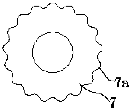
[0018] Such as figure 1 , figure 2 As shown, the inner hole of the branch pipe 1b is a three-stage stepped hole with a small inside and a large outside. The branch spring 4 and the resistor 5 are arranged at the smallest section of the inner hole of the br...


PUM


Abstract

The invention discloses a general engine spark plug cap. An electric conductive cap (3) is in screw thread fit with a min pipe (1a). A screw (6) is an outer hexagon self-tapping screw. Grooves are symmetrically formed in the two ends of a resistor (5). The end of a supporting pipe spring (4) stretches into the groove of one end of the resistor (5), and the other end of the resistor (5) stretches into a countersunk groove in the head of the screw (6). A plum-shaped sheet (7) is fixedly arranged at the position, close to the head of the screw, of the screw (6) in a sleeved mode. The edge of the plum-shaped sheet (7) deforms and is bent towards the tip of the screw (6) to form a circle of cambered surface turnup, and outer teeth (7a) are evenly distributed on the cambered surface turnup in the circumferential direction. The general engine spark plug cap can be assembled at normal temperature, operation workers are prevented from being scalded, residues in the body are easy to remove, and poor breakover of products can be prevented effectively; the contact area between the resistor and the supporting pipe spring and the contact area between the resistor and the screw are large, the contact performance is better, and the therefore breakover performance can be further improved.

Description

technical field [0001] The invention relates to an engine component, in particular to a spark plug cap on a general engine. Background technique [0002] The spark plug cap is an important part of the general engine. It is used to connect the high voltage line and the spark plug. Its quality directly affects the starting performance of the general engine. Chinese patent ZL 200820098167.6 disclosed a spark plug cap for a general-purpose engine on March 18, 2009. A main pipe spring, a retaining spring and a conductive cap are installed in the main pipe of the body, and branch springs, resistors and screws are installed in the branch pipe of the body. The above structure The disadvantages are: [0003] 1) The conductive cap is fixed in the main tube of the main body by interference fit, which is inconvenient to disassemble and assemble, and the assembly efficiency is low; [0004] 2) The screw has a round head structure, which must be assembled at a high temperature in a hot ...

Claims


Application Information

Patent Timeline
Patent Type & Authority Applications(China)
IPC IPC(8): H01T13/04
Inventor 李从仁
Owner CHONGQING CONGREN ELECTROMECHANICAL
Why Eureka
Try Eureka