Wire fixing clamp

A wire fixing clip and wire hook technology, which is applied in the field of wire fixing clips, can solve the problems of leaking sharp edges of sheet metal and easy falling off of sponges, etc.

Active Publication Date: 2014-12-24
GREE ELECTRIC APPLIANCES INC
View PDF9 Cites 9 Cited by
  • Summary
  • Abstract
  • Description
  • Claims
  • Application Information

AI Technical Summary

Problems solved by technology

[0004] In the embodiment of the present invention, a wire fixing clip is provided, which can solve the problems in the prior art that the damping block

Method used


Image

  • Wire fixing clamp
  • Wire fixing clamp
  • Wire fixing clamp

Examples


Embodiment Construction

[0024] The present invention will be described in further detail below in conjunction with the accompanying drawings and specific embodiments, but not as a limitation of the present invention.

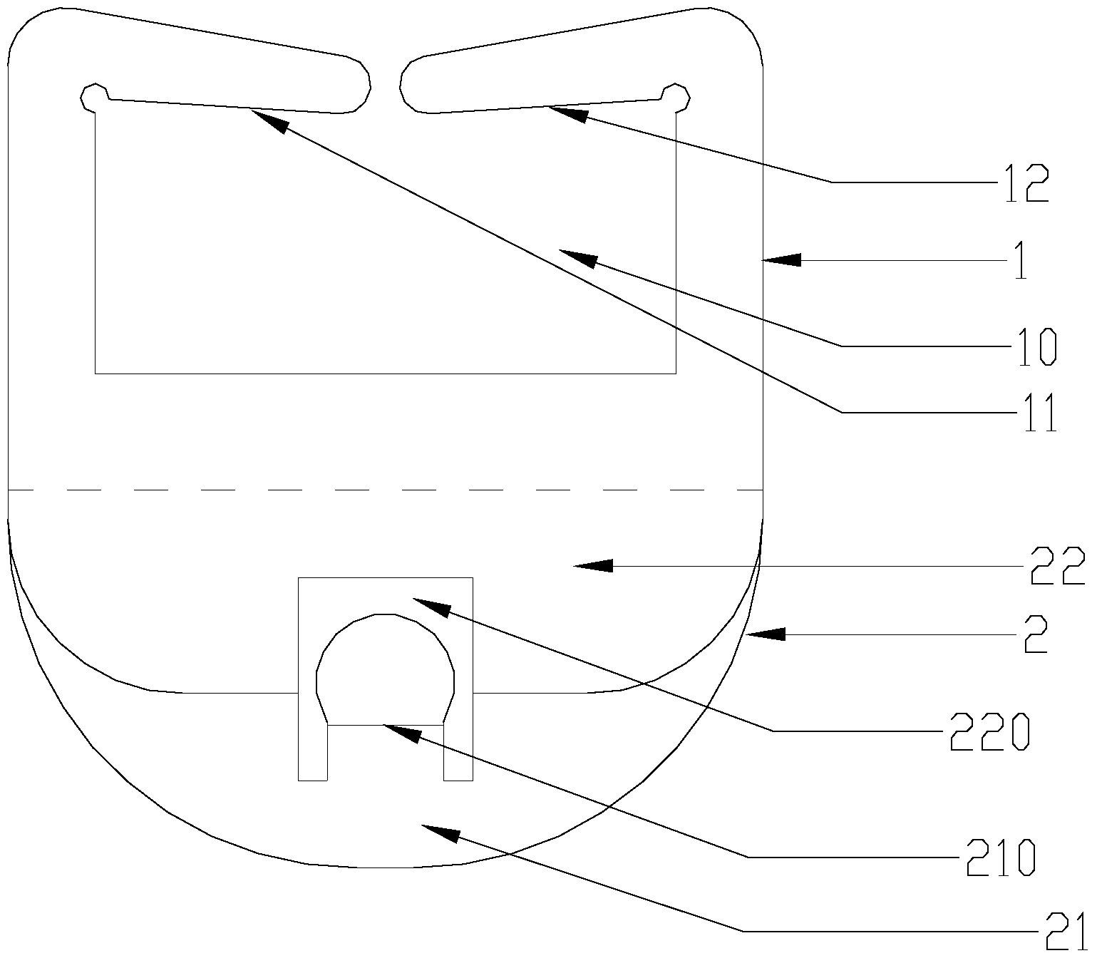
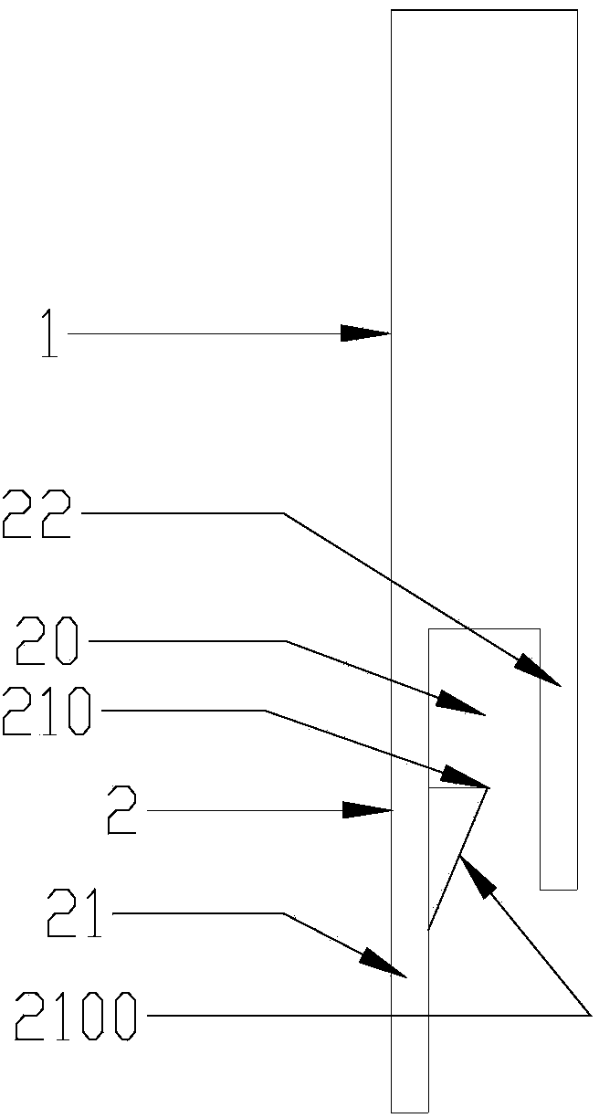
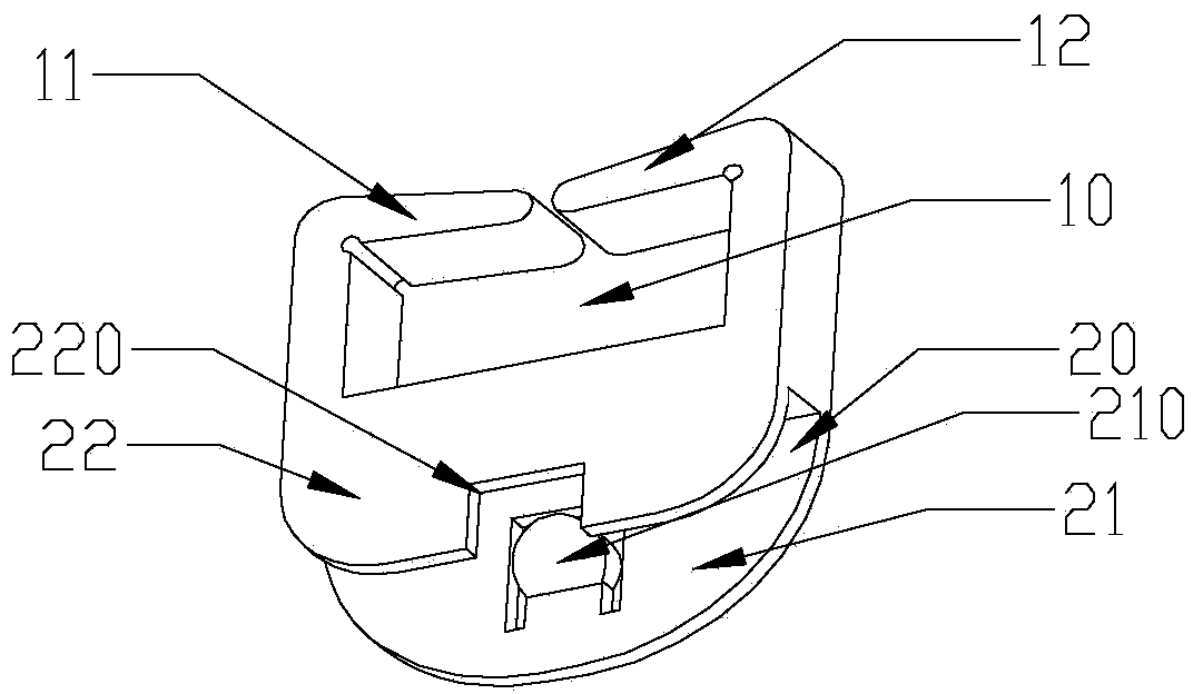
[0025] figure 1 It is a schematic diagram of the front view structure of the wire fixing clip according to the embodiment of the present invention; figure 2 It is a schematic diagram of the side view structure of the wire fixing clip according to the embodiment of the present invention; image 3 It is a three-dimensional structure schematic diagram of the wire fixing clip according to the embodiment of the present invention. Such as figure 1 , figure 2 and image 3 As shown, the wire fixing clip provided in this embodiment is divided into the installation part 2 and the wire fixing part 1 fixedly connected with the installation part 2 , the installation part 2 is arranged on the sharp edge of the sheet metal, and the electric wire is arranged on the wire fixing part 1 . The moun...


PUM


Abstract

The invention discloses a wire fixing clamp which comprises an installation portion and a wire fixing portion fixedly connected with the installation portion. The installation portion is arranged on the sharp edge of a metal plate. A wire is arranged on the wire fixing portion. The installation portion wraps the sharp edge of the metal plate so that the method that a damping block or a piece of sponge is usually attached to the sharp edge can be replaced. The problem that when wrapping of the damping block and the sponge is manually controlled, the sharp edge is prone to exposure due to wrapping deviation is solved; meanwhile, the problems that when the damping block or the sponge is disengaged due to poor viscosity and falls into a unit, the performance of the whole machine is influenced, and even the more serious potential electrical safety hazard is caused are solved.

Description

technical field [0001] The invention relates to the technical field of electrical equipment accessories, in particular to a wire fixing clip for fixing wires from a sharp edge of a sheet metal. Background technique [0002] When the wiring passes through the sharp edge of the sheet metal, because the sheet metal part is too sharp, or the insulation quality of the wire is poor, electrical safety accidents such as wire leakage due to the insulation of the wire are prone to occur. The usual protection method is to cover the sharp edge of the sheet metal with adhesive tape, damping blocks, etc.; or to wrap tape on the insulation to improve its anti-cutting performance. (For example, the motor wire of the air conditioner's inner unit usually crosses the sharp edge of the sheet metal of the bracket. Since the motor wire is easily scratched by the sharp edge of the bracket, the insulation skin is easily scratched. The usual method is to use a damping block or a sponge to paste it o...

Claims


Application Information

Patent Timeline
IPC IPC(8): H02G3/22
Inventor 林智星黄国新谭兵关德灿田立帅余华王红亮谢宝胜
Owner GREE ELECTRIC APPLIANCES INC
Why Eureka
Try Eureka