Bus duct plug box

A plug-in box and busway technology, which is applied in the installation of busbars, electrical components, cables, etc., can solve problems such as inability to install and use, heavy hand feeling, and inconvenient maintenance

Active Publication Date: 2014-12-24
镇江西门子母线有限公司
View PDF10 Cites 11 Cited by
  • Summary
  • Abstract
  • Description
  • Claims
  • Application Information

AI Technical Summary

Problems solved by technology

[0004] The above-mentioned prior art realizes the opening and closing control of the internal switch on the side of the plug-in box, but not only has the disadvantages of loose contact between the slot plate and the switch or the switch slipping, and inconvenient maintenance, but also has the following problems
[0005] 1) The upper part of the switch (also known as a circuit breaker) needs enough space, otherwise it cannot accommodate actuating components such as rocker brackets, so the volume is large, and it cannot be installed and used in a space with a small height
[0006] 2) The hand feels heavy when operating, and the switch is likely to have poor follow-up performance due to wear and tear on the linkage contact parts

Method used


Image

  • Bus duct plug box
  • Bus duct plug box
  • Bus duct plug box

Examples


Embodiment 1

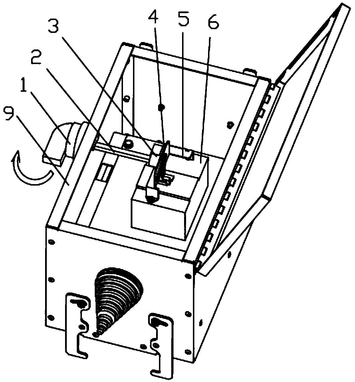
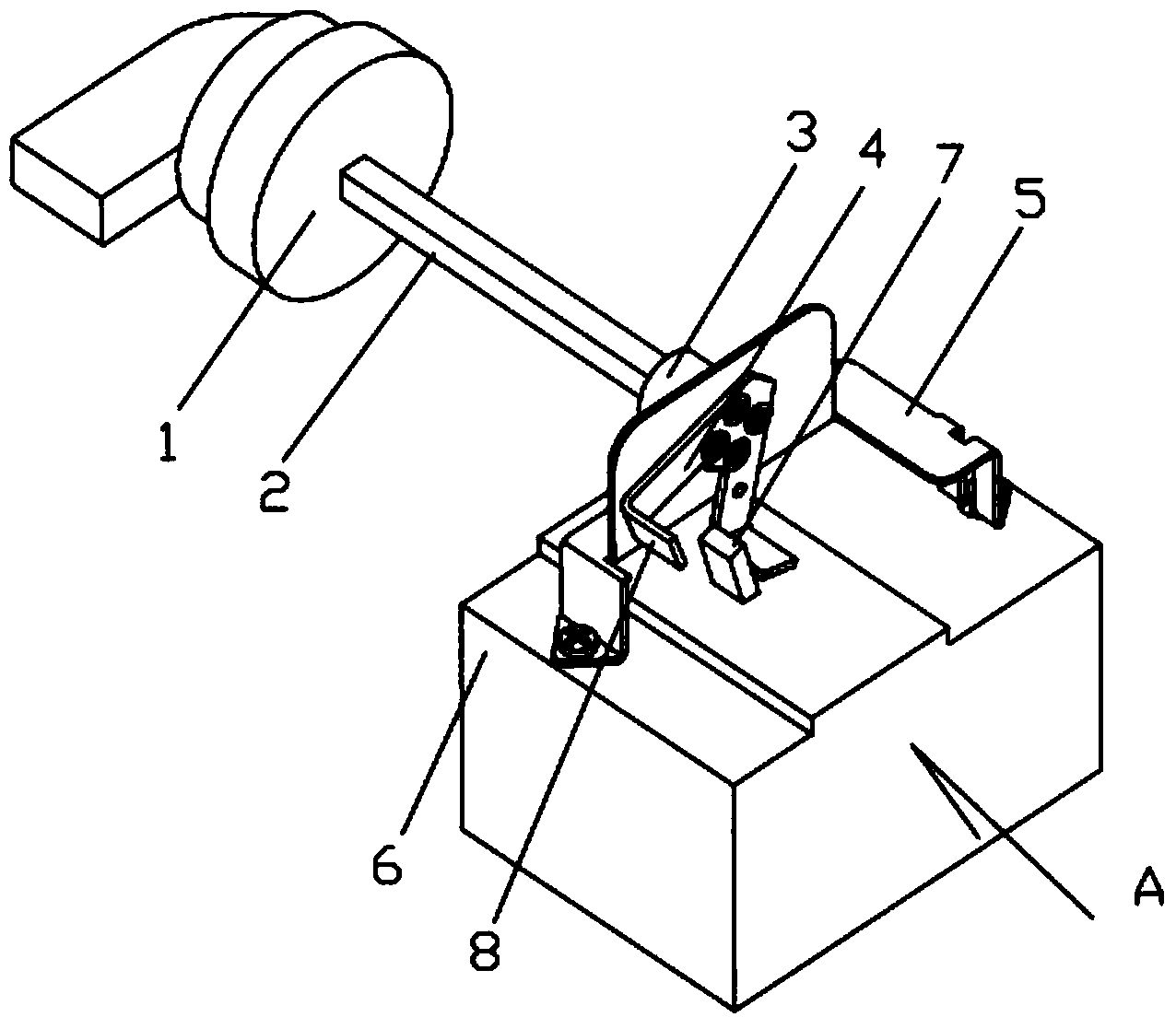
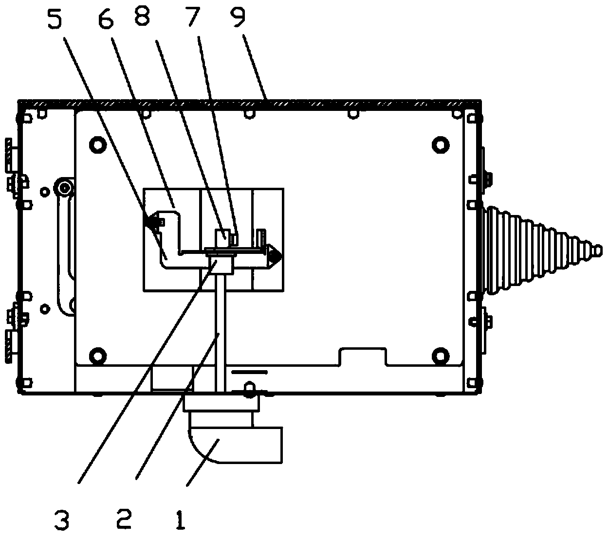
[0025] The busway plug-in box of this embodiment is as follows: figure 1 , figure 2 As shown, it includes a circuit breaker 6 placed in the box 9, and the circuit breaker 6 has a switch handle 7 protruding from the upper surface. The circuit breaker 6 in the casing 9 supports the main rotating shaft 2 with one end protruding from one side of the casing 9 through a hand-operated bracket 5 . The hand-operated support 5 is composed of an upright support surface and support feet fixed on the circuit breaker 6 on both sides.

[0026] The protruding outer end of the main rotating shaft 2 is fixedly connected with the rotary handle 1, and the inner end is fixedly connected with the guide claw 4 through the transmission section 3 through four self-tapping screws. The guide claw 4 is in the shape of an inverted V, and the lower ends of the two forks extend horizontally from the fingers 8 located on both sides of the switch handle 7 .

[0027] When operating, the opening and closing...

Embodiment 2

[0031] The basic structure of the busway plug-in box of this embodiment is the same as that of the first embodiment. The difference is as Figure 7 , Figure 8 As shown, the axis O1 of the main shaft 2 and the rotation axis O2 of the switch handle 7 are in the same vertical plane, and the side of the finger 8 adjacent to the switch handle 7 extends a fingertip 10 with a circular arc head. And the fingertip 10 has an extended slope p gradually expanding from the arc head toward the direction of the finger 8 . When the switch handle 7 is in the extreme position, for example Figure 7 In the closed position shown, the extended slope p is attached to one side of the switch handle 7 . The limit position switch trigger 7 has the longest resistance arm and needs to overcome the resistance generated by its internal spring, so toggling the switch trigger 7 is the most laborious and the most likely to cause wear. The extension slope fits one side of the switch handle so that the for...


PUM


Abstract

The invention relates to a bus duct plug box and belongs to the technical field of electrical connection facilities. The plug box comprises a breaker arranged in a box body, the breaker is provided with a switching gate handle extending out of the upper surface of the breaker, a main rotary shaft is supported in the box body, one end of the main rotary shaft extends out of one side of the box body, the outer extending end of the main rotary shaft is fixedly connected with a rotary handle, the inner extending end of the main rotary shaft is fixedly connected with guide jaws, and the lower ends of the guide jaws horizontally extend to form poking fingers located on the two sides of the switching gate handle respectively. Due to adoption of the sideward arrangement structure, the upper portion of the breaker does not need to have space for holding rocker supports and other actuation components and the structure is compact. Additionally, points where the poking fingers exert force on the switching gate handle are gradually moved downwards in the poking process, the length of a resistance arm of the switching gate handle is reduced while the lengths of power arms of the guide jaws are kept unchanged, and it is guaranteed that follow-up performance of the switching gate handle is better.

Description

technical field [0001] The invention relates to a bus duct plug-in box, in particular to a side-operated plug-in box, which belongs to the technical field of electrical connection facilities. Background technique [0002] With the development of power transmission and distribution business, users have higher and higher requirements on the performance and operation mode of busway plug-in box products. The structure of the traditional plug-in box makes it possible to operate the internal circuit breaker only through the operating mechanism on the door of the plug-in box. When the installation and operation space is insufficient or the user has special operating requirements, the above-mentioned traditional structure will be powerless. [0003] For this reason, Chinese patent applications with application numbers 200810234688.4 and 200910166752.4 have invented a manual operation mechanism for a plug-in box, which consists of an operating handle, an indicator plate, a rotating s...

Claims


Application Information

Patent Timeline
Patent Type & Authority Applications(China)
IPC IPC(8): H02G5/00
Inventor 陶杰祝敏王宁朱建龙张强陈晓艳
Owner 镇江西门子母线有限公司
Why Eureka
Try Eureka