A busway plug-in box
A plug-in box and busway technology, which is applied in the installation of busbars, electrical components, cables, etc., can solve the problems of inconvenient maintenance, inability to install and use, loose contact between the slot plate and the switch, etc.
- Summary
- Abstract
- Description
- Claims
- Application Information
AI Technical Summary
Problems solved by technology
Method used
Image
Examples
Embodiment 1
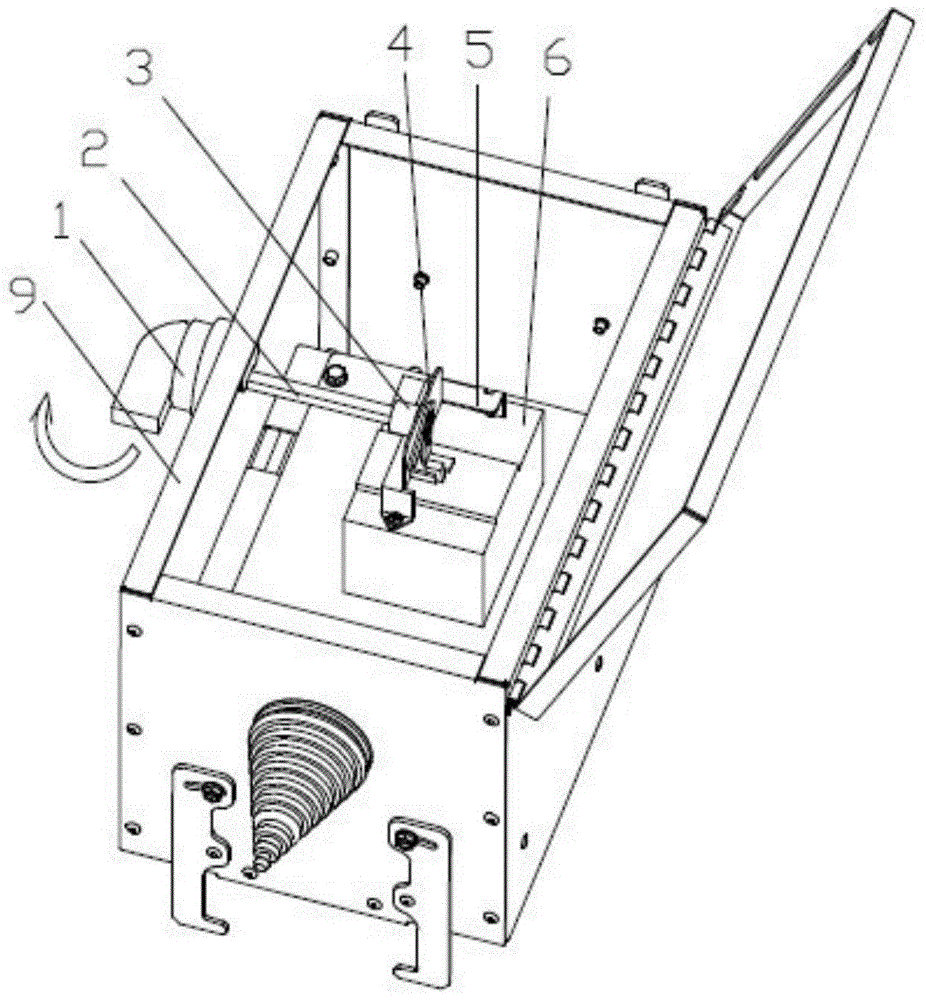
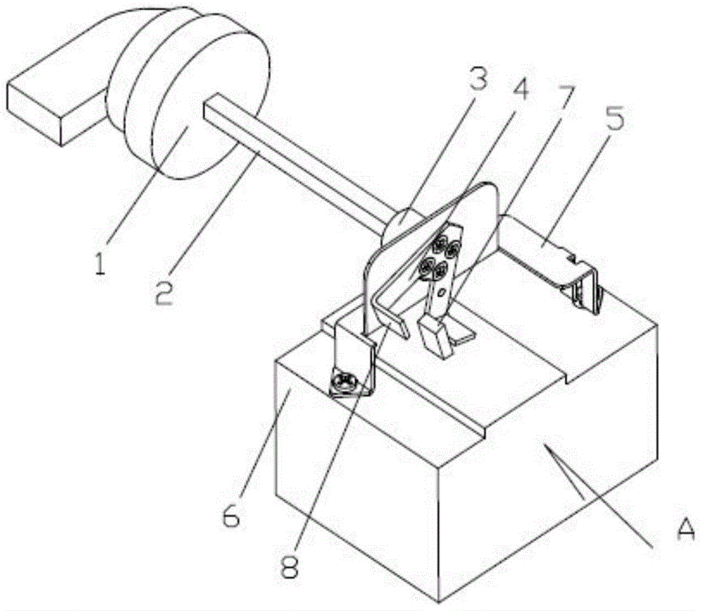
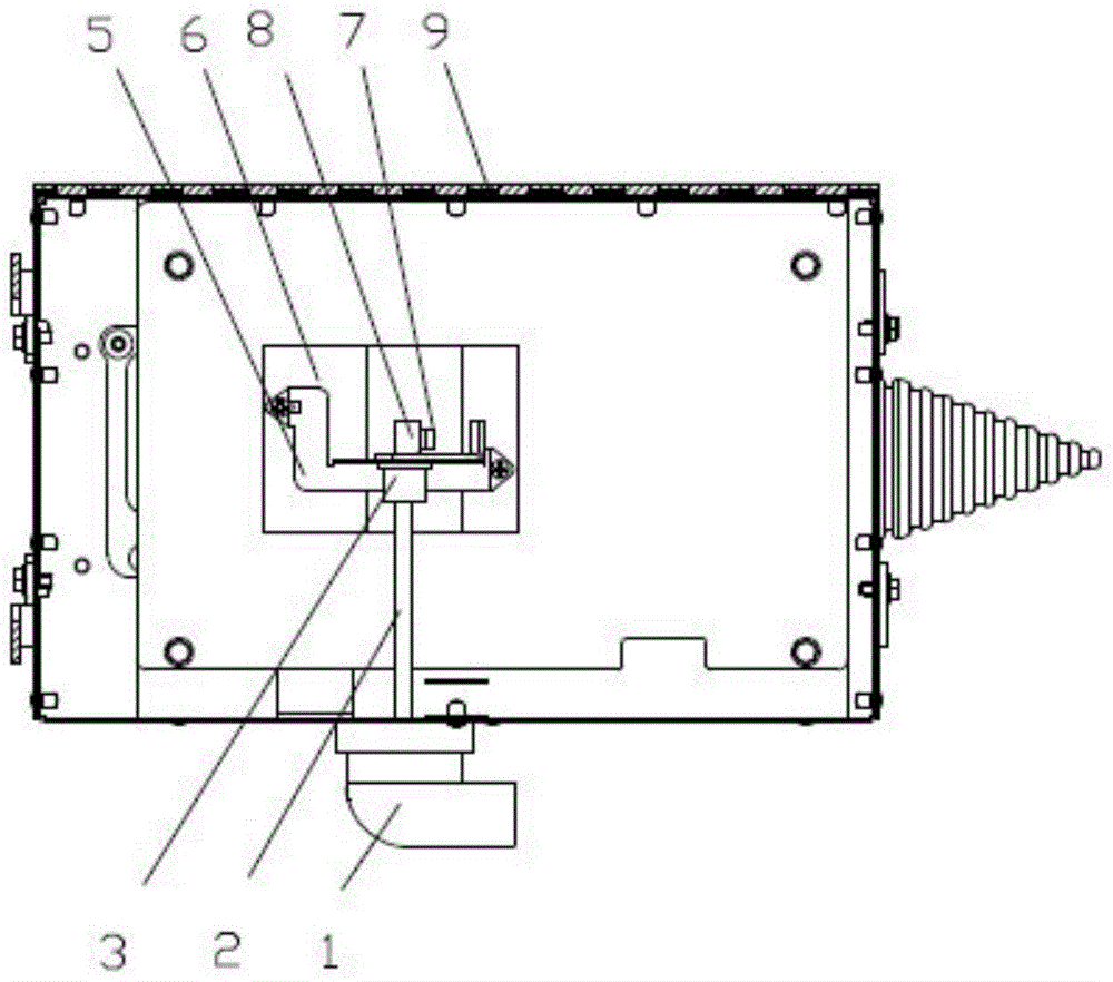
[0025] The busway plug-in box of this embodiment is as follows: figure 1 , figure 2 As shown, it includes a circuit breaker 6 placed in the box 9, and the circuit breaker 6 has a switch handle 7 protruding from the upper surface. The circuit breaker 6 in the casing 9 supports the main rotating shaft 2 with one end protruding from one side of the casing 9 through a hand-operated bracket 5 . The hand-operated support 5 is composed of an upright support surface and support feet fixed on the circuit breaker 6 on both sides.
[0026] The protruding outer end of the main rotating shaft 2 is fixedly connected with the rotary handle 1, and the inner end is fixedly connected with the guide claw 4 through the transmission section 3 through four self-tapping screws. The guide claw 4 is in the shape of an inverted V, and the lower ends of the two forks extend horizontally from the fingers 8 located on both sides of the switch handle 7 .
[0027] When operating, the opening and closing...
Embodiment 2
[0031] The basic structure of the busway plug-in box of this embodiment is the same as that of the first embodiment. The difference is as Figure 7 , Figure 8 As shown, the axis O1 of the main shaft 2 and the rotation axis O2 of the switch handle 7 are in the same vertical plane, and the side of the finger 8 adjacent to the switch handle 7 extends a fingertip 10 with a circular arc head. And the fingertip 10 has an extended slope p gradually expanding from the arc head toward the direction of the finger 8 . When the switch handle 7 is in the extreme position, for example Figure 7 In the closed position shown, the extended slope p is attached to one side of the switch handle 7 . The limit position switch trigger 7 has the longest resistance arm and needs to overcome the resistance generated by its internal spring, so toggling the switch trigger 7 is the most laborious and the most likely to cause wear. The extension slope fits one side of the switch handle so that the for...
PUM
 Abstract
Description
Claims
Application Information
 - R&D
- Intellectual Property
- Life Sciences
- Materials
- Tech Scout
- Unparalleled Data Quality
- Higher Quality Content
- 60% Fewer Hallucinations
Browse by: Latest US Patents, China's latest patents, Technical Efficacy Thesaurus, Application Domain, Technology Topic, Popular Technical Reports.
© 2025 PatSnap. All rights reserved.Legal|Privacy policy|Modern Slavery Act Transparency Statement|Sitemap|About US| Contact US: help@patsnap.com


