
Charge and discharge control device and method and electric automobile swapping station

A charge-discharge control and control target technology, applied in the field of micro-grid, can solve problems such as low regulation efficiency and failure to fully consider the randomness of renewable energy output, and achieve the effects of improving reliability, reducing uncertainty, and improving utilization

Inactive Publication Date: 2014-12-24
HITACHI LTD
View PDF1 Cites 4 Cited by
  • Summary
  • Abstract
  • Description
  • Claims
  • Application Information

AI Technical Summary

Problems solved by technology

The control method mainly sets the common external output of the photovoltaic power generation system (that is, the photovoltaic power generation unit described later in the present invention) and the energy storage system (that is, the energy storage device described later in the present invention) as a constant output target value, but does not fully consider The output of renewable energy is random, and there is a problem of low regulation efficiency

Method used

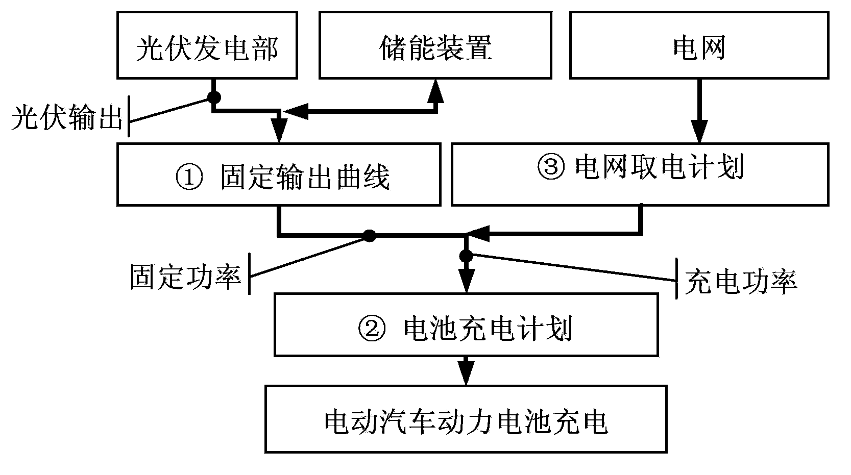
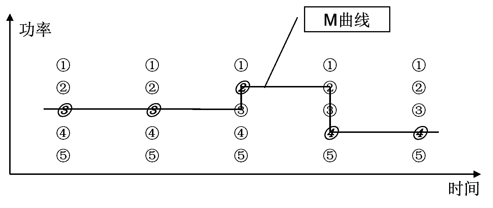

Image

  • Charge and discharge control device and method and electric automobile swapping station
  • Charge and discharge control device and method and electric automobile swapping station
  • Charge and discharge control device and method and electric automobile swapping station

Examples


Embodiment Construction

[0023] Embodiments of the present invention will be described below with reference to the drawings. However, the following embodiment is only an example of the present invention, and the scope of protection required by the present invention is not limited by the embodiment.

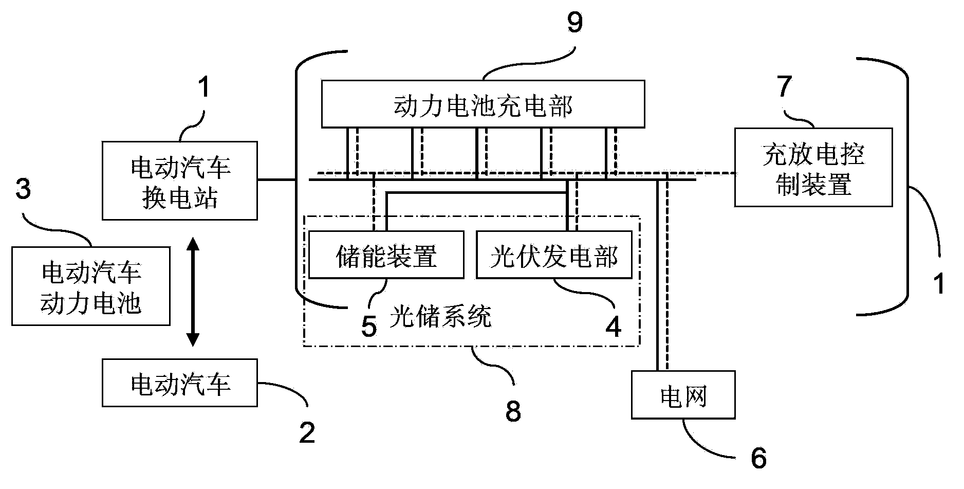
[0024] figure 1 It is a block diagram showing the overall structure of the light-storage electric vehicle substation to which the charge-discharge control device of the present invention is applied. in, figure 1 The left side shows the situation that the electric vehicle 2 drives into the electric vehicle exchange station 1, and the power battery 3 that has been used up or is about to be used up is replaced with a battery that has been fully charged by the exchange station. figure 1 The right side shows the general structure of the electric vehicle swapping station 1 .

[0025] In the electric vehicle swap station 1, the photovoltaic power generation unit 4, the energy storage device 5, and the vehicle...


PUM


Abstract

The invention provides a charge and discharge control device and method and an electric automobile swapping station. The charge and discharge control device controls a light storage system. The light storage system is connected into a power grid and composed of a photovoltaic power generation portion and an energy storage device. The charge and discharge control device comprises a storage portion, a light storage system initial value target calculation portion, a light storage system target correction portion and a control portion, wherein the storage portion stores historical data information of a plurality of control periods of the output power of the photovoltaic power generation portion, the light storage system initial value target calculation portion calculates a control target initial value curve of the output power of the light storage system of the next control period according to the historical data information stored in the storage portion, the light storage system target correction portion corrects the control target initial value curve according to charge and discharge power information and the capacity of the energy storage device to obtain a control target value curve of the output power of the light storage system, and the control portion controls the charge and discharge of the energy storage device so as to enable the output of the light storage system to conform to the control target value curve of the light storage system.

Description

technical field [0001] The invention relates to a charging and discharging control device, a method and an electric vehicle swapping station, in particular to a charging and discharging controlling device and a method suitable for a light-storage electric vehicle charging and swapping station, and belongs to the field of microgrids. Background technique [0002] With the rapid development of electric vehicles, the problem of charging the batteries used is also oncoming. In the charging mode of electric vehicles, there are generally two modes: charging mode and battery swapping mode. Among them, the charging type refers to the way that the electric vehicle is charged by an external power supply after entering the charging station, which will take a long time; and the battery swapping type refers to the way that the electric vehicle enters the charging station, and it takes a short time to replace it with the existing one. By means of a battery that has been charged by a swap...

Claims


Application Information

Patent Timeline
Patent Type & Authority Applications(China)
IPC IPC(8): H02J7/00H02J3/28
CPCY02E10/56Y02E70/30
Inventor 于跃张靖李超
Owner HITACHI LTD
Learn More