Manufacturing process of magnetic rotor in magnetic pump

A technology of internal magnetic rotor and manufacturing process, applied in the direction of manufacturing stator/rotor body, etc., can solve the problems of high scrap rate, high manufacturing cost and affecting welding quality, etc.

Active Publication Date: 2018-04-13
安徽星球盛唐泵业有限公司
View PDF6 Cites 8 Cited by
  • Summary
  • Abstract
  • Description
  • Claims
  • Application Information

AI Technical Summary

Problems solved by technology

Due to the existence of the magnetic block, spatter will be generated during welding, which will affect the welding quality. In addition, due to internal stress factors, defects will be formed after cooling, which cannot be remedied, the scrap rate is high, and the production cost is high.

Method used


Image

  • Manufacturing process of magnetic rotor in magnetic pump
  • Manufacturing process of magnetic rotor in magnetic pump
  • Manufacturing process of magnetic rotor in magnetic pump

Examples


Embodiment Construction

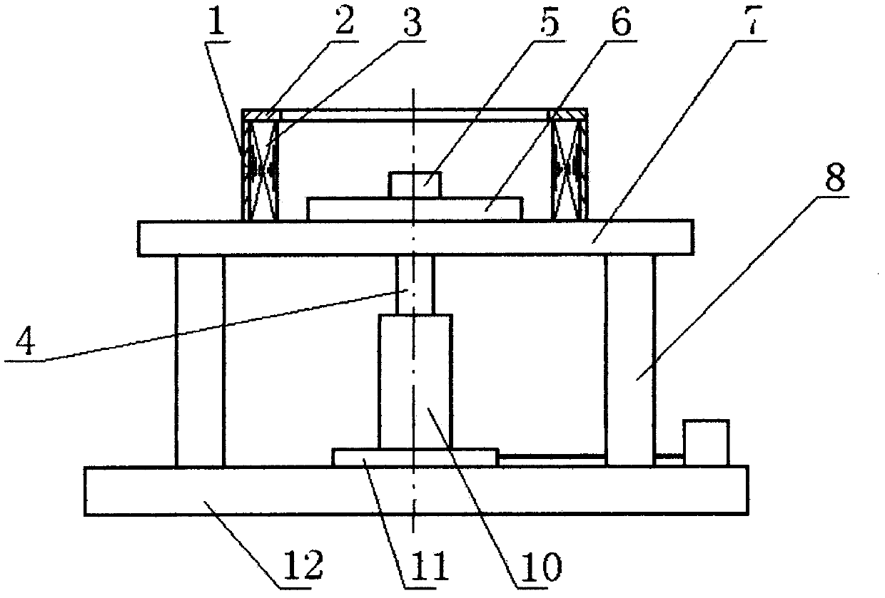
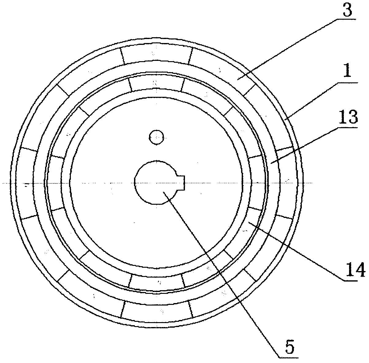
[0018] The manufacturing process of the magnetic rotor in the magnetic force pump of the present invention, the steps are as follows: a, make the welding frock of the magnetic rotor in the magnetic force pump, such as figure 1 , figure 2 As shown, the welding tooling of the magnetic rotor in the magnetic pump includes a bracket 8, a magnetic circuit closing part and an internal magnetic rotor lifting mechanism, the magnetic circuit closing part is located above the bracket 8, the lower part of the bracket 8 is the base 12, and the upper part of the bracket 8 is the top plate 7. The magnetic circuit closing part includes a metal outer ring 1, a pressure plate 2, and inlaid magnetic blocks 3 having the same number as the magnetic blocks of the inner magnetic rotor 14. The inlaid magnetic blocks 3 are arranged on the inner surface of the metal outer ring 1, and two adjacent inlaid magnetic blocks The N pole and the S pole are opposite, the pressure plate 2 is located above the ...


PUM


Abstract

The invention discloses a manufacturing process of an inner magnetic rotor of a magnetic force pump. The steps are as follows: a. Manufacturing welding tooling for the inner magnetic rotor of a magnetic force pump; , and then spot-weld the sheath baffle, the sheath and the rotor seat to form the inner magnetic rotor blank of the magnetic pump; c, pick up the inner magnetic rotor blank of the magnetic pump and place it on the welding tooling of the inner magnetic rotor of the magnetic pump; d, Weld the cover baffle with the rotor seat, and weld the left and right ends of the cover with the rotor seat and the cover baffle respectively to make a semi-finished part of the inner magnetic rotor of the magnetic pump; e. Machine the semi-finished part of the inner magnetic rotor of the magnetic pump After processing and passing the inspection, the finished magnetic rotor in the magnetic pump is obtained. The manufacturing process of the magnetic rotor in the magnetic pump of the present invention adopts such a method that spatter does not occur during welding, which can ensure welding quality, eliminate product scrapping caused by internal stress, improve product qualification rate, and reduce manufacturing cost.

Description

technical field [0001] The invention relates to a pump, in particular to a manufacturing process of a magnetic rotor in a magnetic pump. Background technique [0002] The magnetic pump is composed of a pump, a magnetic driver and a motor. The magnetic driver includes an inner magnetic rotor, an outer magnetic rotor and an isolation sleeve. When the motor drives the outer magnetic rotor to rotate, the magnetic field can penetrate the air gap and non-magnetic materials, and drive the impeller to rotate. The connected internal magnetic rotors rotate synchronously to realize the non-contact transmission of power, thereby pumping liquid. Such as image 3 As shown, the magnetic rotor in the magnetic pump includes a rotor base 15, a magnetic flux coil 20, a plurality of magnetic blocks 17, a spacer 18, a cover 16 and a cover baffle 19, the rotor base 15 has a shaft hole, and the middle part of the rotor base 15 There is a magnetic flux circle 20, and a plurality of magnetic blocks...

Claims


Application Information

Patent Timeline
Patent Type & Authority Patents(China)
IPC IPC(8): H02K15/03
Inventor 李刚唐剑杨承嗣张胜君
Owner 安徽星球盛唐泵业有限公司
Why Eureka
Try Eureka