Eureka AIR delivers breakthrough ideas for toughest innovation challenges, trusted by R&D personnel around the world.

Friction stir welding method for lock bottom circular seam of carrier rocket storage tank

A technology of friction stir welding and launch vehicle, which is applied in the field of friction stir welding, which can solve the problems of poor plastic metal fluidity at the root of the weld, weak stirring ability, and the lock bottom structure is not suitable for the friction stir welding process, etc., and achieves the consistency of mechanical properties and Improved stability and improved performance

Active Publication Date: 2015-03-25
CAPITAL AEROSPACE MACHINERY +1
View PDF6 Cites 14 Cited by
  • Summary
  • Abstract
  • Description
  • Claims
  • Application Information

AI Technical Summary

Problems solved by technology

However, there will be some problems when the friction stir welding technology is directly applied to the existing storage tank bottom lock joint structure, which is mainly reflected in the following aspects: (1) From a structural point of view, the lock bottom joint includes a 1 / 2 lap joint, However, the stirring ability at the end of the friction stir welding tool used in engineering is weak at present, resulting in poor fluidity of the plastic metal at the root of the weld, so it is easy to cause the insertion of the plug-in joint to extend toward the inside of the weld, which is not conducive to the improvement of the performance of the joint; ( 2) The length of the stirring needle, the position of the fork ring or the short shell on the forward side have a great influence on the mechanical properties of the joint during actual welding; (3) the existing locking bottom structure is not suitable for the friction stir welding process, and structural improvement is required

Method used


Image

  • Friction stir welding method for lock bottom circular seam of carrier rocket storage tank
  • Friction stir welding method for lock bottom circular seam of carrier rocket storage tank
  • Friction stir welding method for lock bottom circular seam of carrier rocket storage tank

Examples


Embodiment Construction

[0024] A friction stir welding method for locking the bottom ring seam of a carrier rocket storage tank, comprising the following steps:

[0025] Step 1: Transform the welded parts

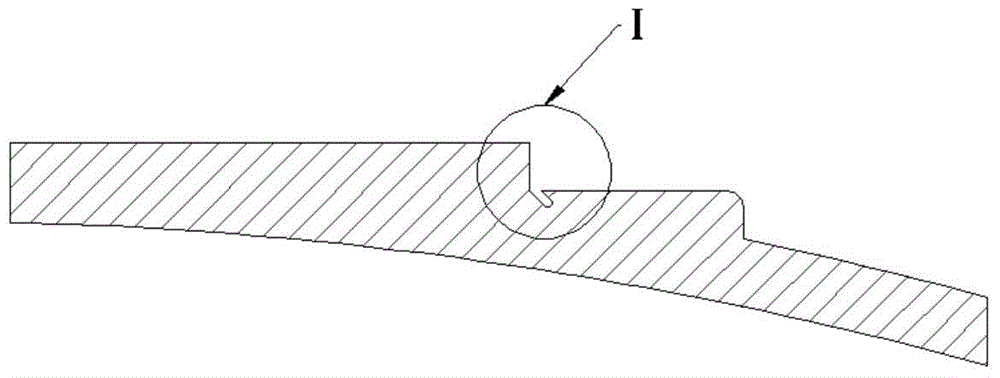
[0026] Open the welding leakage groove 4 on the fork ring 2 at the bottom of the box. The welding leakage groove 4 is set at the bottom of the welding seam of the fork ring 2 at the bottom of the box, and is 45° from the welding seam. The width range of the welding leakage groove 4 is 1.0-1.5mm, and the vertical depth 1.5~2.0mm.

[0027] Step 2: Welding parts overlap

[0028] The welded bottom fork ring 2 and the short shell 3 are lapped together to form a weld.

[0029] Step 3: Soldering

[0030] Weld along the seam by friction stir welding.

[0031] Welding requirements are: ① During friction stir welding, place the fork-shaped ring 2 at the bottom of the box on the forward side of the weld (that is, the rotation direction of the stirring tool on the side of the fork-shaped ring 2 at the bot...


PUM

PropertyMeasurementUnit
Widthaaaaaaaaaa
Vertical depthaaaaaaaaaa

Abstract

The invention belongs to welding methods, and particularly relates to a friction stir welding method for a lock bottom circular seam of a carrier rocket storage tank. The method comprises the following steps that firstly, welded parts are transformed, welding leakage grooves are formed in a tank bottom fork-shaped ring, and the welding leakage grooves are formed in the bottommost portion of a tank bottom fork-shaped circular welding seam; secondly, the welded parts are in lap joint, and the welded tank bottom fork-shaped ring is in lap joint with a short shell to form the welding joint; thirdly, welding is carried out, and welding is carried out along the welding joint through the friction stir welding manner. The method has the obvious advantages that nearly defect-free welding can be achieved, the consistency and stability of the mechanical property of the joint are obviously improved, and compared with a fusion welding lock bottom joint, the performance of the lock bottom circular seam is improved by about 20 percent to 30 percent.

Description

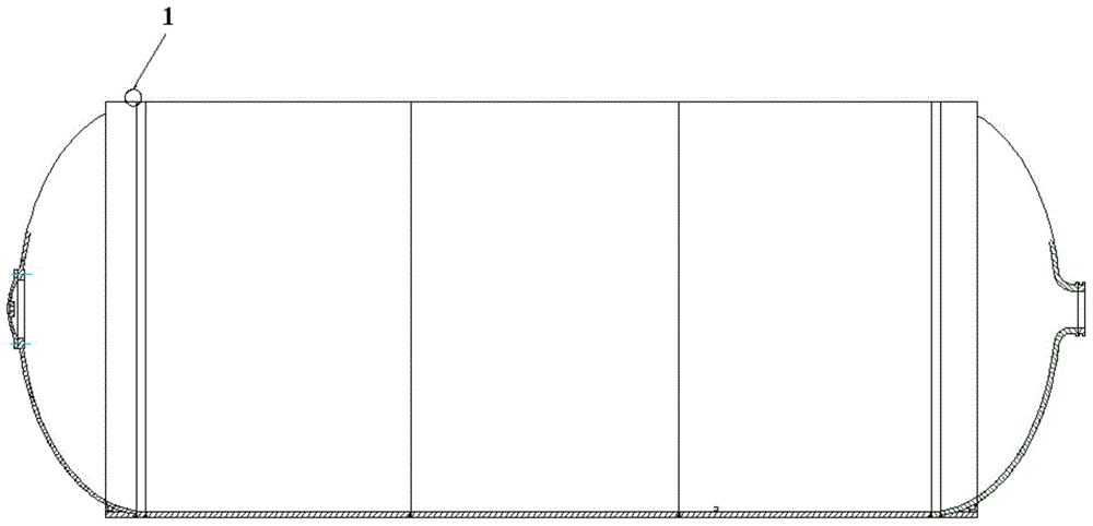
technical field [0001] The invention belongs to a welding method, and in particular relates to a friction stir welding method for locking the bottom ring seam of a storage tank of a carrier rocket. Background technique [0002] The bottom lock ring seam of the launch vehicle tank is a ring seam connecting the front (rear) short shell of the tank and the fork ring at the bottom of the front (rear) tank. Compared with the type I butt ring seam of the storage tank, the structural form of the lock bottom ring seam joint is more special (such as figure 1 , 2 As shown), there is a plug joint between the short shell and the fork ring at the bottom of the box, and the front side of the weld is beveled. The bottom lock ring seam of the active series of launch vehicles in my country mainly adopts the fusion welding process to penetrate once. Although the existing bottom lock structure and fusion welding process can meet the product requirements, there are many problems in the botto...

Claims


Application Information

Patent Timeline
IPC IPC(8): B23K20/12
CPCB23K20/122B23K20/1255B23K2101/12
Inventor 王国庆郝云飞李延民赵衍华周庆王伟马建波苏磊
Owner CAPITAL AEROSPACE MACHINERY
Why Eureka
Eureka Blog
Learn More