Permanent magnet speed regulation, braking or load device with adjustable coupled magnetic flux

A load device, permanent magnet speed regulation technology, applied in the direction of permanent magnet clutch/brake, sustainable manufacturing/processing, climate sustainability, etc., can solve the problem of poor reliability, limited application field of permanent magnet speed regulation technology, technical performance more demanding issues

Inactive Publication Date: 2016-12-28
林英楠
View PDF6 Cites 2 Cited by
  • Summary
  • Abstract
  • Description
  • Claims
  • Application Information

AI Technical Summary

Problems solved by technology

[0004] 1. Large installation size, high requirements for on-site installation conditions of technical transformation projects, and poor adaptability
[0005] 2. The existing known permanent magnet speed governor, permanent magnet brake and permanent magnet load device, because the coupling distance and / or coupling area of ​​the air gap magnetic field constructed between the permanent magnetic disk and the permanent magnetic coupling disk by directly adjusting are Real-time online dynamic changes, so at least one of the passive disk and the driving disk and its transmission shaft is an axial sliding and torque transmission structure, this structure brings great difficulties to product manufacturing and assembly processes The technical indicators such as material and manufacturing precision of key components are relatively strict, the manufacturing process is complicated, and the manufacturing cost remains high; The technical performance requirements of configuring the actuator are relatively high
[0006] 3. In the speed regulation section of 35-75% of the rated speed, the permanent magnet coupling component of the existing permanent magnet speed governor is seriously heated, and it is easy to generate local high heat during use, so it cannot be applied to occasions with high explosion-proof requirements ; On the other hand, when the coupling air gap distance of the permanent magnetic coupling component is large or the coupling area is small (less than 70% of the adjustment stroke section), the system vibration is large, which will cause serious consequences of poor reliability
[0007] 4. The known permanent magnet speed governor cannot realize the speed-up adjustment function, which limits the application field of permanent magnet speed regulation technology
[0008] 5. The known permanent magnet speed regulation, braking and load devices have complex structures and poor reliability

Method used


Image

  • Permanent magnet speed regulation, braking or load device with adjustable coupled magnetic flux
  • Permanent magnet speed regulation, braking or load device with adjustable coupled magnetic flux
  • Permanent magnet speed regulation, braking or load device with adjustable coupled magnetic flux

Examples


Embodiment 1

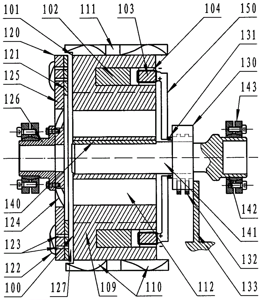
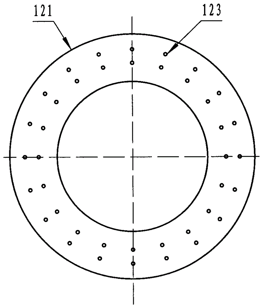
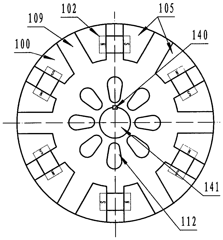
[0090] Such as figure 1 , 2 , 3 and 4 and Figure 56 , Figure 57 , Figure 58 or Figure 59 As shown, it is a turntable-type permanent magnet speed-adjustable coupling composed of a single-layer single-sided permanent magnet coupling assembly of "a group of axial magnetic fields", which is mainly composed of a permanent magnet coupling disc ( 120). The flux switching permanent disk (101) used as a passive disk is composed. The permanent magnet coupling disc (120) is composed of an axial magnetic field metal conductor armature disc (121) and a yoke back disc (125). The flux switching permanent disc (101) consists of a permanent disc body (109) and eight sets of permanent magnets (102) and eight groups of magnetic flux switches used to control the bypass of the permanent magnet coupling magnetic flux path. The magnetic flux switch is composed of an electromagnet core (103), an electromagnet coil (104) and a yoke (105). The ferromagnetic poles (N, S) are in the same direction as ...

Embodiment 2

[0093] Such as Figure 5 , 6 , 7 and 8 and Figure 56 , Figure 57 , Figure 58 or Figure 59 As shown, it is a turntable type permanent magnet brake / load device with adjustable coupling magnetic flux composed of a single-layer single-sided permanent magnet coupling component of "a group of axial magnetic fields", which is mainly composed of a permanent magnet coupling disc used as a brake disc (220). The magnetic flux switching permanent disk (201) is used as the active disk. The permanent magnet coupling disk (220) is composed of an axial magnetic field grate type armature disk (221) and a yoke back disk (225). The magnetic flux switch type permanent disk (201) is composed of a permanent disk body (209) and eight permanent disks. The magnet (202) and eight sets of magnetic flux switches for controlling the bypass of the permanent magnet coupling magnetic flux path. The magnetic flux switches are composed of an electromagnet core (203), an electromagnet coil (204) and a yoke (2...

Embodiment 3

[0096] Such as Picture 9 , 10 , 11, 12 and 13 and Figure 56 , Figure 57 , Figure 58 or Figure 59 As shown, it is a rotating drum-type permanent magnetic coupling with adjustable coupling magnetic flux composed of a single-layer single-sided permanent magnetic coupling assembly of "a group of radial magnetic fields", which is mainly composed of a permanent magnetic coupling disc used as an active disc (320). Flux switching permanent disk (301) used as a passive disk is composed. The permanent magnetic coupling disk (320) is composed of a radial magnetic field metal conductor armature disk (321) and a yoke back disk (325). The magnetic flux switching permanent disk (301) is composed of a permanent disk body (309) and eight sets of U ”Type neodymium iron boron permanent magnet (302) and eight sets of magnetic flux switches (303, 304) used to control the bypass of the permanent magnet coupling magnetic flux path. The magnetic flux switch consists of an electromagnet core (303) ...


PUM


Abstract

The invention relates to a permanent-magnet speed regulation, braking or loading apparatus with an adjustable coupled flux. The apparatus is characterized in that a driving plate is a permanent-magnet coupling plate and a driven plate or braking plate is a flux switch type permanent-magnet plate; or the flux switch type permanent-magnet plate is used as a driving plate and the permanent-magnet coupling plate is used as driven plate / braking plate. The permanent-magnet coupling plate and the flux switch type permanent-magnet plate are in an air gap and magnetic field coupling structure mode; the installing sequences of the permanent-magnet coupling plate and the flux switch type permanent-magnet plate can be interchanged; and both the permanent-magnet coupling plate and the flux switch type permanent-magnet plate can serve as the driving plate and driven plate respectively and the internal and external nesting positions of the two plates also can be interchanged. The provided apparatus can be applied to technical fields like coupling transmission and load speed regulation, an automatic transmission unit, braking, rotary loading, power cutting off / combination, electromotor energy saving, household appliances, a sealed pump, petrochemical engineering, and wind power generation and the like; and the technical scheme employed by the apparatus can be used for designing and manufacturing a permanent-magnet speed controller, a speed-regulation coupler, an automatic transmission unit, a brake device, a loading / unloading device, a centrifugal load speed regulator or clutch, or a novel energy-saving household appliance.

Description

Technical field [0001] The technical fields involved in the present invention include: transmission shaft coupling drive / transmission and speed regulation technical field, automatic transmission field of vehicles, energy saving and emission reduction technical field, petroleum pumping unit technical field, cutting / combining power technical field, isolation / sealing Transmission field, braking and braking technology field, power equipment dynamometer load / load, household appliances (including air conditioners, electric fans, washing machines) and other technical fields, wind power / internal combustion engine / hydropower technology fields, and electric motors drive generators to generate power / change In the field of electrical technology, especially a permanent magnet speed control, braking or load device that can adjust the coupling magnetic flux. Background technique [0002] Around us, permanent magnet speed regulation, braking and load devices can be applied to coupling transmissi...

Claims


Application Information

Patent Timeline
Patent Type & Authority Patents(China)
IPC IPC(8): H02K49/10
CPCY02P20/10
Inventor 林英楠
Owner 林英楠
Why Eureka
Try Eureka