
A Method of Responding to Network Congestion Based on Network Jitter Algorithm

A technology of network congestion and jitter algorithm, applied in the field of network transmission, can solve problems such as inability to timely and accurately feedback network conditions, inability to timely and obvious network congestion, inability to respond sensitively to network jitter, etc., to reduce packet loss rate and enhance robustness performance and avoid packet loss

Active Publication Date: 2017-11-17
厦门亿联通讯技术有限公司
View PDF4 Cites 0 Cited by
  • Summary
  • Abstract
  • Description
  • Claims
  • Application Information

AI Technical Summary

Problems solved by technology

The jitter calculation method in the existing RFC3550 protocol is to differentiate the sending timestamp and receiving timestamp of two adjacent packets. This method cannot indicate network congestion in a timely and obvious manner. From the mathematical model, it is Calculate the difference between the transmission delays of two adjacent packets, and then perform exponential smoothing on the absolute value of the difference. The final result is the network jitter value. This method of calculating the jitter value cannot sensitively reflect the network jitter. Only when the arriving packet delay is positive and negative alternately, can the congestion situation be reflected. If several positive delay packets are continuously received and then several negative delay packets are continuously received, the network situation cannot be timely and accurately fed back. However, when bandwidth is congested in actual video applications, this situation is often more likely to occur.

Method used


Image

  • A Method of Responding to Network Congestion Based on Network Jitter Algorithm
  • A Method of Responding to Network Congestion Based on Network Jitter Algorithm
  • A Method of Responding to Network Congestion Based on Network Jitter Algorithm

Examples


Embodiment Construction

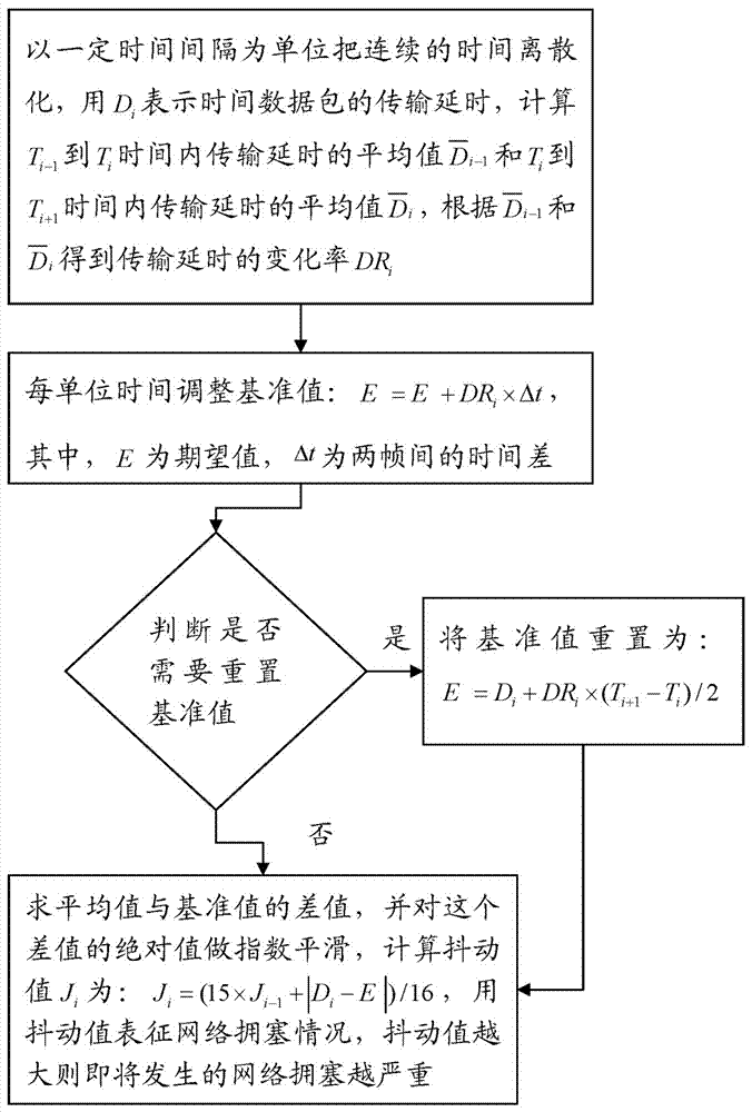
[0028] Please refer to figure 1 with figure 2 , a method for reflecting network congestion based on a network jitter algorithm, the method characterizes the jitter value by calculating the difference between the transmission delay of the data packet and the reference value, and then predicts the network congestion situation through the jitter value, the reference value For the expected value of transmission delay within a set time, the method includes the following steps:

[0029] Step 10, discretize the continuous time with a time interval as the unit, and use the frame as the discretized time unit in the video application, T i to T i+1 A total of 20 frames in the time interval, use D i Indicates the transmission delay of the data packet, the transmission delay D i The calculation formula is: D i =(R i -S i ), where R i is the receiving time in timestamp units when the receiving end receives the RTP packet, S i The RTP packet comes with a timestamp, indicating the s...


PUM


Abstract

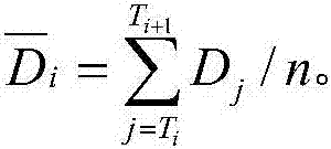
The invention provides a network dithering algorithm based network congestion reflection method. The method includes the steps: step 10, taking a certain time interval as a unit for time discretization of continuous time, taking Di as transmission delay of data packets to calculate an average value of transmission delay from Ti-1 to Ti and an average value of transmission delay from Ti to Ti+1, and obtaining a change rate DRi of transmission delay according to the two average values; step 20, adjusting a reference value per unit time: E=E+DRi*delta t, wherein E refers to a value of expectation, delta t refers to time difference between two frames; step 30, judging whether the reference value needs to be reset or not, and if yes, resetting the reference value according to an equation: E=Di+DRi*(Ti+1-Ti) / 2; step 40, calculating a dithering value Ji according to an equation: Ji=(15*Ji-1+|Di-E|) / 16, and using the dithering value to represent network congestion conditions, wherein the larger the dithering value, the more serious the impending network congestion. By the network dithering algorithm based network congestion reflection method, network congestion conditions can be reflected timely and accurately, and sensitivity to network congestion is improved to lower packet loss rate.

Description

technical field [0001] The invention relates to the technical field of network transmission, in particular to a method for reflecting network congestion based on a network jitter algorithm. Background technique [0002] At present, with the rapid development of information technology and fierce competition among major operators, the optical fiber network has been greatly popularized. However, as the competition for network bandwidth resources becomes more and more fierce, the bandwidth is insufficient, which affects users in the process of real-time multimedia communication. For this reason, most developers of real-time multimedia communication applications currently use network adaptive technology to adjust the current bandwidth used to match the actual available bandwidth of the network, thereby reducing network packet loss and jitter when the available bandwidth is insufficient. To achieve the purpose of improving user experience, the network adaptive algorithm generally ...

Claims


Application Information

Patent Timeline
Patent Type & Authority Patents(China)
IPC IPC(8): H04L12/26
Inventor 贺于峰梁二振
Owner 厦门亿联通讯技术有限公司
Learn More