Digital television signal receiving device

A digital TV signal and receiving device technology, applied in the field of antenna devices, can solve the problems of complex erection and disassembly, large structural size, heavy weight, etc., and achieve the effect of improving the aesthetics of room decoration, flexible use, and simple structure

Inactive Publication Date: 2014-12-24
常州金坛达昇工贸有限公司
View PDF0 Cites 0 Cited by
  • Summary
  • Abstract
  • Description
  • Claims
  • Application Information

AI Technical Summary

Problems solved by technology

[0004] Under the conditions of satisfying the electrical and mechanical properties, the traditional antenna usually has a large structural size and heavy weight. At the same time, as the height of the antenna increases, its structural size and weight increase sharply, resulting in complicated erection and disassembly, let alone satisfying portable requirements

Method used


Image

  • Digital television signal receiving device
  • Digital television signal receiving device
  • Digital television signal receiving device

Examples


Embodiment 1

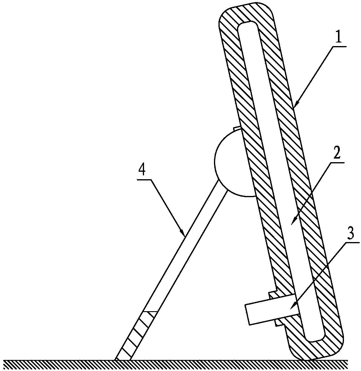
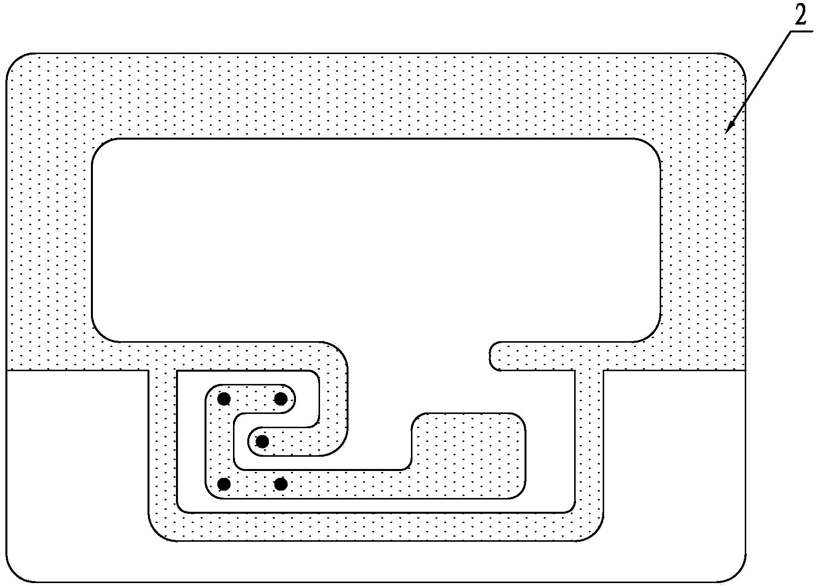
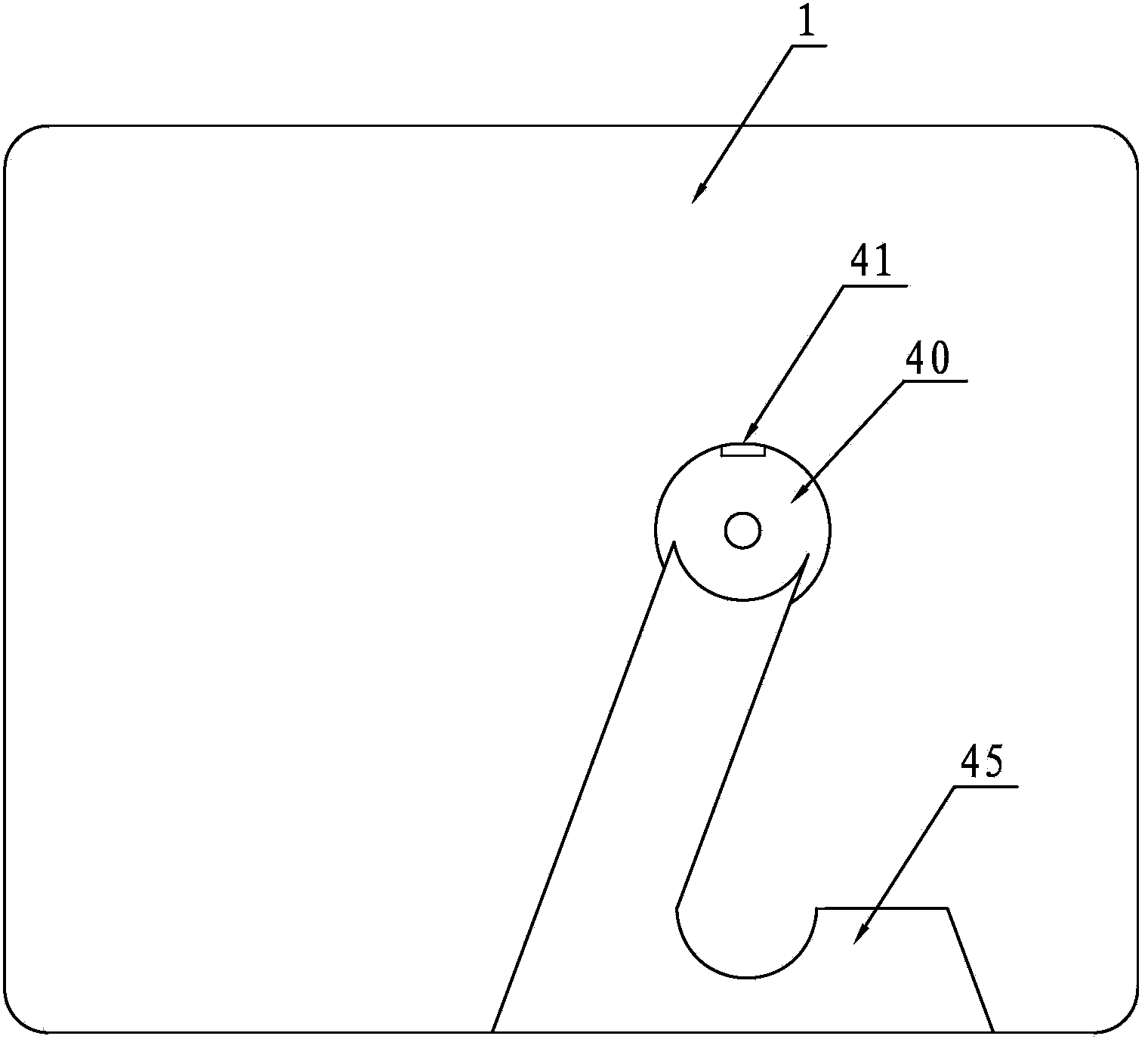
[0019] A digital television signal receiving device, comprising a cover case 1, a signal receiving board 2, a signal connector 3 and a support member 4, the signal receiving board 2 is placed in the cover case 1, and a connector is provided on the back of the cover case 1 The sleeve 11 and the rotating connection cavity 12, the signal connector 3 is electrically connected with the signal receiving board 2 and is set in the joint sleeve 11, the support member 4 is installed in the rotating connection cavity 12, and the rotating connection cavity 12 is circular, and the rotating connection The cavity 12 is provided with an inner rotating ring 13, an outer rotating ring 14, a small circumferential limiting groove 15, a large circumferential limiting groove 16 and a rotating mandrel 17. The outer rotating ring 14 is arranged above the inner rotating ring 13, and the circumferential direction The small limiting grooves 15 are evenly distributed on the inner rotating ring 13, the lar...


PUM


Abstract

A digital television signal receiving device comprises a cover, a signal receiving board, a signal joint and a supporting part, wherein the signal receiving board is placed in the cover, the back side of the cover is provided with a joint sleeve and a rotating connection cavity, the signal joint and the signal receiving board are electrically connected and installed in the joint sleeve in a sleeved mode, an inner rotating ring, an outer rotating ring, a small circumferential limiting groove, a large circumferential limiting groove and a rotating mandrel are arranged in the rotating connection cavity, the supporting part comprises a connecting convex ring, a limiting die block, a die block fixing part, a fixing sleeve, a spring and a supporting leg, the rotating mandrel is sleeved with the fixing sleeve, the limiting die block is provided with a limiting convex block, an inner limiting end face and an outer limiting end face, the limiting convex block is in running fit with the inner rotating ring, the outer limiting end face is in running fit with the outer rotating ring, the limiting convex block is arranged in the small circumferential limiting groove, the inner limiting end face abuts against the outer rotating ring, and the limiting die block is placed in the large circumferential limiting groove. The digital television signal receiving device is small in size, can be placed indoors at will, be taken at will and be freely folded and unfolded, and has the good decorative function.

Description

technical field [0001] The invention relates to an antenna device, in particular to a digital TV signal receiving device. Background technique [0002] All devices that use electromagnetic waves to transmit information require antennas. Therefore, in the fields of broadcasting, communications, meteorology, aerospace, and electronic countermeasures, antennas become a key component of the system. [0003] At present, there are many forms and types of digital antennas, among which pot-type antennas and telescopic rod-type antennas are the most widely used. With the increasing number of portable equipment, people's requirements for antennas are getting higher and higher. Antennas must not only have excellent electrical signal receiving functions, but also be easy to erect, disassemble and decorate. Small, easy to erect and collect, but also has good decorative performance. [0004] Traditional antennas, under the conditions of satisfying electrical and mechanical properties, u...

Claims


Application Information

Patent Timeline
Patent Type & Authority Applications(China)
IPC IPC(8): H04N5/44H04N21/41
Inventor 蒋志军
Owner 常州金坛达昇工贸有限公司
Why Eureka
Try Eureka