Worm-gear clamp with spiral spring

A technology of helical spring and worm gear, which is applied in the direction of sleeve/socket connection, pipe/pipe joint/pipe fitting, passing element, etc. It can solve the problems of difficult processing, low installation efficiency, small spring adjustment, etc., and reach the installation position The effect of low requirements, small space occupied by bolts and large spring adjustment

Active Publication Date: 2014-12-31
CHONGQING YIGE PIPELINE TECH
View PDF7 Cites 1 Cited by
  • Summary
  • Abstract
  • Description
  • Claims
  • Application Information

AI Technical Summary

Problems solved by technology

After the clamp is installed in place, the spring can be compressed to store energy by tightening the nut. When the rubber hose becomes loose, the spring rebounds to compensate for the gap, which is equivalent to secondary tightening. This method is the most widely used, but the disadvantages are: 1. The clamping range is limited by the length of the bolt, the clamping range is small, and the effective diameter adjustment range is only about 7mm, which often results in different pipe diameters requiring many specifications of clamps, which waste a lot of time in design selection, transportation, warehouse and on-site management. 2. The bandwidth of the clamp is super wide, generally 19mm, and some installation positions are less than 19mm, which makes installation difficult
3. The size of the fastening nut is different from that of the worm clamp bolt head with the largest amount of conventional applications. It is necessary to replace the installation tool during installation, resulting in a decrease in installation efficiency
4. The length of the bolt is long, and one end protrudes, which takes up a lot of space, and cannot be installed in some small spaces.
5. It is impossible to produce pipe clamps with a diameter less than 40mm
[0004] The second type of clamp is a radial spring worm screw clamp, such as image 3 and Figure 4 As shown, the structural principle is that on the basis of the worm clamp, a radial spring is set on the surface of the inner ring of the clamp, so that energy is stored from the radial spring during fastening, and the radial spring returns when the hose shrinks and a gap occurs. The advantages of the clamp are: 1. The clamp makes up for the shortcoming of the T-type clamp, that is, the small adjustment range, and the adjustment range can reach more than 20mm; 2. The clamp overcomes the T-type clamp. The bandwidth is wide, and some places cannot be installed; 3. The clamp overcomes the disadvantage that the bolt head is different from the ordinary clamp bolt head, and the installation tool needs to be replaced, and the installation efficiency is high; 4. The bolt length is short and takes up little space. However, there are also some new disadvantages: 1. The radial spring belongs to unilateral compensation, which cannot realize 360° compensation, and there is a risk of leakage under high pressure; 2. Unilateral compensation will lead to compensation when the size is large (that is, the diameter is large). The effect is not good; 3. The assembly torque cannot be made large
But it also brings new disadvantages: 1. Because the processing is difficult and the technical requirements are high, the cost is high, which is about 3 times that of T-shaped clamps and radial spring clamps; 2. The adjustment range of the disc spring is smaller than T When the shrinkage gap of the hose is larger than the adjustable range of the disc spring, the disc spring clamp will not be able to compensate the hose gap in the whole process; 3. In order to increase the breaking torque, the installed bolt head is larger than the ordinary installation bolt head Large, cannot be used universally with installation tools, and installation efficiency is low; 4. The outer diameter of the disc spring is large, resulting in teeth gnawing when the band is unscrewed, resulting in a large free torque during assembly
[0006] In summary, the existing clamps with adjustment and compensation functions have the following defects: 1. The clamping range is small; 2. The adjustment amount of the spring is small; 3. It cannot realize 360° all-round compensation; 4. The clamp The bandwidth is too large, and some installation positions are not enough; 5. The breaking torque is too small; 6. The cost is high; 7. The size of the bolt head is not uniform, and the installation efficiency is low; 8. The outer diameter of the disc spring is too large, and the teeth are chewed during assembly Causes free torque to be too large
9. Bolts take up a lot of space

Method used


Image

  • Worm-gear clamp with spiral spring
  • Worm-gear clamp with spiral spring
  • Worm-gear clamp with spiral spring

Examples


Embodiment Construction

[0022] The present invention will be further described in detail below in combination with specific embodiments.

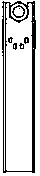
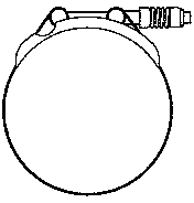
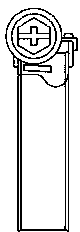
[0023] As a preferred embodiment of the present invention, such as Figure 7-Figure 8As shown, a helical spring turbine worm clamp includes a band 1 and a band seat 2, and the inner cavity of the band seat 2 has a cylindrical part for installing the worm and a grooved part for fixing the band 1, One end of the band 1 is fixed in the groove-shaped part of the band seat 2, and the other end of the band 1 is provided with a section of worm teeth along the length direction. The belt 1 is bent to form a circular turbine, and a worm 3 is installed on the hoop 2. The worm 3 has a rotating force application end positioned outside the hoop 2 and an engaging end inserted into the inner cavity of the cylindrical part of the hoop 2. On the engaging end It has a section of meshing teeth and meshes with the worm teeth on the band 1, the rotating force end of the worm 3 and the...


PUM


Abstract

The invention discloses a worm-gear clamp with a spiral spring. The worm-gear clamp comprises a washer, the spiral spring, a bolt, a clamping strip and a clamping block. The clamping strip is bent into a round worm wheel; the clamping block is provided with a worm bolt having a meshing end inserted into an inner cavity of the clamping block; the meshing end is provided with meshing teeth meshing with worm teeth of the clamping strip; the rotation forcing end of the worm bolt is sleeved with the spiral spring; the washer sleeving the worm bolt is arranged between the spiral spring and the clamping block; the washer matches with the spiral spring in diameter; the rotation forcing end of the worm bolt is provided with a bolt head; the inner side of the bolt head matches with the spiral spring in diameter so that two ends of the spiral spring are abutted between the bolt head and the washer. The worm-gear clamp has the advantages such that a clamping range is wide, spring adjustment is great, comprehensive compensation can be achieved, the requirement on a mounting position is low, breaking torque is greater, cost is low, mounting efficiency is high, the fact that tooth gnawing occurring in assembly affects free torque is avoided, and the bolt needs small space.

Description

technical field [0001] The invention relates to a clamp for connecting a pipeline system, in particular to a coil spring turbine worm clamp for connecting a pipeline system with a large temperature difference between cold and heat. Background technique [0002] Existing fuel-powered equipment, such as automobiles, construction machinery, generators, agricultural machinery, etc., will have fuel systems, intake and exhaust systems, cooling systems, cooling and heat exchange systems, lubrication systems, etc., which need to be connected by pipelines during work. . Some of these systems work with relatively large temperature changes, such as exhaust systems, cooling systems, and cold and heat exchange systems. When the pipelines of the cooling system and the cooling and heat exchange system are connected, rubber tube sleeves are generally used to connect outside the metal tubes, and the two ends are clamped with clamps. Since the temperature of the above-mentioned pipeline sys...

Claims


Application Information

Patent Timeline
Patent Type & Authority Applications(China)
IPC IPC(8): F16L21/06
CPCF16L21/00
Inventor 唐维明
Owner CHONGQING YIGE PIPELINE TECH
Why Eureka
Try Eureka