An antenna alignment method and system

An antenna and antenna fixing technology, which is applied in the field of communication, can solve the problems of high requirements for skills and work experience, increased difficulty in aligning antennas with narrow beam antennas, and long alignment time

Active Publication Date: 2016-11-23
HUAWEI TECH CO LTD
View PDF9 Cites 0 Cited by
  • Summary
  • Abstract
  • Description
  • Claims
  • Application Information

AI Technical Summary

Problems solved by technology

[0003] With the application of the microwave unlicense frequency band, the carrier frequency band is greatly increased, the beam is narrowed, and the main lobe of the antenna is significantly reduced, which greatly reduces the range where the multimeter can detect the signal strength. It takes a long time, and the difficulty of antenna alignment for narrow beam antennas is increased compared to wide beam antennas

Method used


Image

  • An antenna alignment method and system
  • An antenna alignment method and system
  • An antenna alignment method and system

Examples


Embodiment Construction

[0063] The following will clearly and completely describe the technical solutions in the embodiments of the present invention with reference to the accompanying drawings in the embodiments of the present invention. Obviously, the described embodiments are only some, not all, embodiments of the present invention. Based on the embodiments of the present invention, all other embodiments obtained by persons of ordinary skill in the art without creative efforts fall within the protection scope of the present invention.

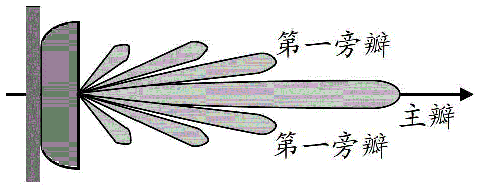
[0064] The electric field intensity radiated by the antenna changes with the space, and this change trend is described as the antenna pattern, which usually has three-dimensional and two-dimensional. The two-dimensional antenna pattern includes the expressions of the horizontal antenna pattern and the vertical antenna pattern, such as figure 1 Shown is the antenna pattern in the vertical direction. Depend on figure 1 It can be seen that there are many lobes in the...


PUM


Abstract

The embodiment of the present invention discloses an antenna alignment method and system. The two antennas aligned with each other first scan the handshake information through the negative signal-to-noise ratio communication mode, and at the same time generate the receiving statistics according to the receiving statistics of the carrier signal. Curve or curved surface, and according to the receiving statistics to generate the curve or curved surface of receiving statistics changing with the angle to determine the rough scan range, and then the antennas at both ends alternately scan to achieve antenna alignment. The invention shortens the alignment time while ensuring the alignment accuracy, saves labor costs, and contributes to the mass application of microwave links.

Description

technical field [0001] The present invention relates to the communication field, in particular to an antenna alignment method and system. Background technique [0002] Antenna alignment refers to adjusting the positions of the two antennas for microwave communication so that the main lobes of the two antennas are aligned. The two antennas for microwave communication are called opposite antennas. At present, the common antenna alignment method is that technicians use a multimeter to measure the received signal strength of the antenna at different angles, and judge the main lobe direction of the antenna based on these data, and then manually adjust the antenna to the main lobe direction. [0003] With the application of the microwave unlicense frequency band, the carrier frequency band is greatly increased, the beam is narrowed, and the main lobe of the antenna is significantly reduced, which greatly reduces the range where the multimeter can detect the signal strength. It ta...

Claims


Application Information

Patent Timeline
Patent Type & Authority Patents(China)
IPC IPC(8): H04B17/11H04B17/21H01Q21/00H01Q3/00
Inventor 肖凌文蔡华何佳徐明慧
Owner HUAWEI TECH CO LTD
Why Eureka
Try Eureka