Power loss calculation method for power cable sheath

A technology of power loss and calculation method, applied in the direction of electric power measurement through current/voltage, etc., can solve problems such as time-consuming, labor-intensive, low-efficiency, and time-wasting

Inactive Publication Date: 2015-01-07
ZHEJIANG UNIV
View PDF8 Cites 2 Cited by
  • Summary
  • Abstract
  • Description
  • Claims
  • Application Information

AI Technical Summary

Problems solved by technology

The more effective method for systematically studying sheath loss is the full-phase model method, but the traditional full-phase model method has the following two problems: 1) It is necessary to establish a node voltage equation in each subdivision, if the model is to be guaranteed Accuracy, the overall voltage equation may be as high as tens of thousands of orders, and

Method used


Image

  • Power loss calculation method for power cable sheath
  • Power loss calculation method for power cable sheath
  • Power loss calculation method for power cable sheath

Examples


Embodiment Construction

[0073] In order to describe the present invention more specifically, the technical solutions of the present invention will be described in detail below in conjunction with the accompanying drawings and specific embodiments.

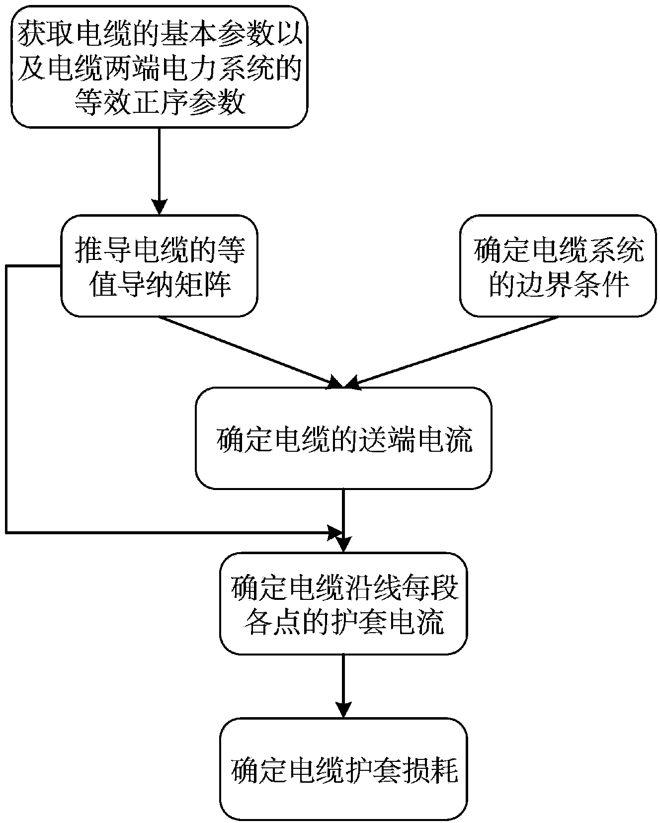
[0074] Such as figure 1 As shown, a power loss calculation method of a power cable sheath includes the following steps:

[0075] (1) Obtain the basic parameters of the cable, including the unit length series impedance matrix Z and the parallel admittance matrix Y, and the equivalent positive sequence parameters of the power system at both ends of the cable include the equivalent power supply amplitude E of the power system at the sending end S , phase θ S and equivalent impedance Z S , the equivalent power amplitude E of the power system at the receiving end R , θ R and equivalent impedance Z R ; The method for solving the above parameters is quite mature, so it is not included in the discussion of the method of the present invention.

[0076] (2) A...


PUM


Abstract

The invention discloses a power loss calculation method for a power cable sheath. An equivalent admittance matrix of a cable is derived according to basic parameters of the cable and the structure of the cable; the current of a cable sending end is calculated and determined according to the equivalent admittance matrix of the cable and boundary conditions of a cable system; the sheath current of each point of each section along the cable is determined according to the current of the cable sending end, and therefore the loss of the cable sheath is determined. Compared with the prior art, the power loss calculation method is short in consumed time and high in precision, the precise distribution condition of voltage and current along the cable can be calculated, the sheath loss of each section of the cable is determined, and a theoretical basis is provided for subsequent cable loss reducing strategies.

Description

technical field [0001] The invention belongs to the technical field of electric power transmission, and in particular relates to a method for calculating power loss of a power cable sheath. Background technique [0002] The power cable transmission method has developed rapidly in recent years, and more and more underground transmission systems are used in the expansion of urban power grids. There are three main reasons: First, the growing environmental problems limit the use of overhead lines in cities. Second, in the field of marine power transmission, submarine cables have incomparable advantages over overhead lines; third, innovations in cable manufacturing and operation technology make insulated cables more competitive. [0003] In single-core cables, the cable sheath protects the single-core conductor from moisture and mechanical damage; in addition, the cable sheath shields electrostatic fields and serves as a return circuit for fault currents and capacitive charging c...

Claims


Application Information

Patent Timeline
IPC IPC(8): G01R21/06
Inventor 徐政林勇肖亮
Owner ZHEJIANG UNIV
Why Eureka
Try Eureka