Automatic positioning and guiding connecting device and method for electric automobile and charging device

A technology for automatic positioning and charging equipment, which is applied to electric vehicle charging technology, electric vehicles, parts of connecting devices, etc. It can solve the problems that charging cables cannot be connected and charged, no literature reports, high position accuracy, etc.

Active Publication Date: 2015-01-07
TIANJIN ZHONGHUAN FUSHI INTELLIGENT EQUIP
View PDF5 Cites 11 Cited by
  • Summary
  • Abstract
  • Description
  • Claims
  • Application Information

AI Technical Summary

Problems solved by technology

[0002] At present, if a charging device needs to be installed in the three-dimensional parking equipment for lifting and traversing, it can only be installed on the ground floor. When it is necessary to charge EVs in the parking spaces above the second floor, there will be a problem that the charging cable cannot be connected for charging.
As a result, in the existing three-dimensional parking equipment, it is impossible to realize EV charging above the second floor, forming a blank application
[0003] If it is necessary to introduce the connector into the three-dimensional parking equipment and carry out the relay of the charging cable to solve it, it will face two problems: (1) the standard connector plug-in has a small allowable error and high position accuracy, and is usually only suitable for manual charging. connect
(2) In the three-dimensional parking equipment, it is impossible to arrange personnel to climb and insert connectors above the second floor
[0004] At present, there is no relevant technical application in this industry, and there are no literature reports

Method used


Image

  • Automatic positioning and guiding connecting device and method for electric automobile and charging device
  • Automatic positioning and guiding connecting device and method for electric automobile and charging device
  • Automatic positioning and guiding connecting device and method for electric automobile and charging device

Examples


Embodiment Construction

[0044] In order to understand the present invention more clearly, describe the present invention in detail in conjunction with accompanying drawing and embodiment:

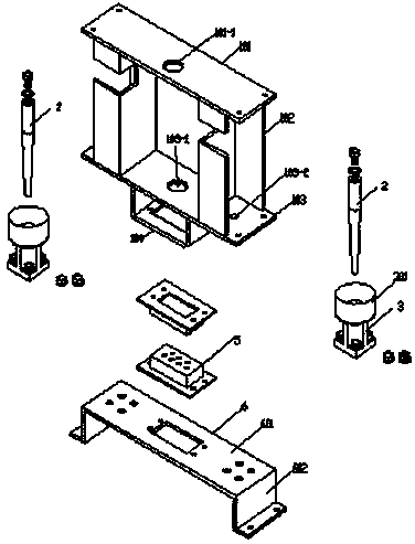
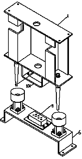
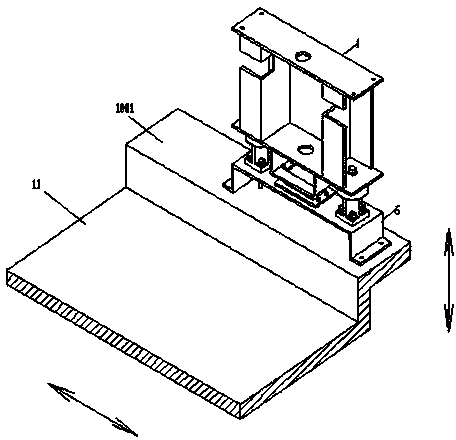
[0045] Such as Figure 1 to Figure 21 As shown, the automatic positioning and guiding connection device between electric vehicles and charging equipment, including fixed parts and moving parts;

[0046] Described fixing part comprises alignment pin fixed frame 1, uses alignment pin fixed frame 1 as the mounting part of alignment pin 2, connector plug 4, and alignment pin fixed frame 1 is made up of upper plate 101, boom 102, base plate 103, U-shaped frame 104; the upper plate 101 is processed with a wire hole A101-1 and a mounting hole, and is fixed on the frame above the parking space in the garage through the mounting hole and bolts;

[0047] The two booms 102 are made of channel steel, the booms 102 are welded between the upper plate 101 and the bottom plate 103, the middle part of the bottom plate 103 is ...


PUM


Abstract

The invention relates to an automatic positioning and guiding connecting device and method for an electric automobile and a charging device. The automatic positioning and guiding connecting device comprises a fixed part and a movable part. The fixed part comprises positioning pin fixing frames serving as installing components of positioning pins and a connector plug. The movable part comprises positioning base fixing frames serving as installing components of positioning bases, positioning hopper platforms and a connector socket. The lower surface of the connector socket is fixedly connected with a charging power socket. A chassis charging power socket is matched with a chassis charging power plug. An automatic positioning correcting mechanism is formed by the positioning pins, the positioning bases and the positioning hopper platforms on the positioning base. Positioning hoppers, the positioning bases and the positioning pins are installed in a chassis and a garage respectively, the error correction capacity is designed for the automatic positioning and guiding connecting device according to a calculating method and a designing formula of the automatic guiding and positioning error correcting capacity to achieve automatic butting of the connecting device, and therefore accurate connection of connectors is achieved.

Description

technical field [0001] The present invention relates to three-dimensional parking equipment, in particular to an automatic positioning guide connection device and method for electric vehicles and charging equipment, which are used to realize electric vehicle charging when an electric vehicle (referred to as EV) is stored in the three-dimensional parking equipment. Background technique [0002] At present, if a charging device needs to be installed in the three-dimensional parking equipment of the lifting and traversing type, it can only be installed on the ground floor. When it is necessary to charge EVs in the parking spaces above the second floor, the problem that the charging cable cannot be connected to charge will be encountered. As a result, in the existing three-dimensional parking equipment, it is impossible to realize EV charging above the second floor, forming a blank application. [0003] If it is necessary to introduce the connector into the three-dimensional par...

Claims


Application Information

Patent Timeline
Patent Type & Authority Applications(China)
IPC IPC(8): H01R13/631H01R43/00H01R43/26
CPCB60L53/16H01R13/631H01R43/00H01R43/26H01R2201/26Y02T10/70Y02T10/7072Y02T90/14
Inventor 尉丽玲任初农李国飞刘思洋
Owner TIANJIN ZHONGHUAN FUSHI INTELLIGENT EQUIP
Why Eureka
Try Eureka