Fabric for airbag and fabric roll
A fabric roll and fabric technology, applied in fabrics, textiles and papermaking, fabric surface trimming, etc., can solve the problems of friction reduction yarn, difficulty in exerting opening suppression, and no introduction of high temperature openings, etc., to achieve the effect of uniform air flow
- Summary
- Abstract
- Description
- Claims
- Application Information
AI Technical Summary
Problems solved by technology
Method used
Image
Examples
Embodiment 1
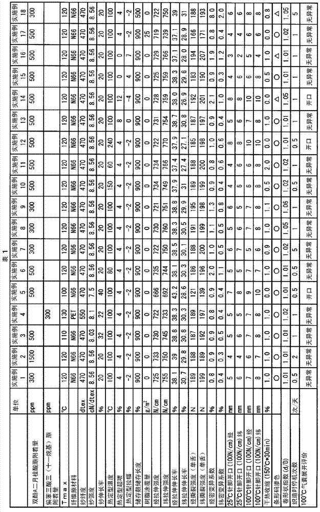
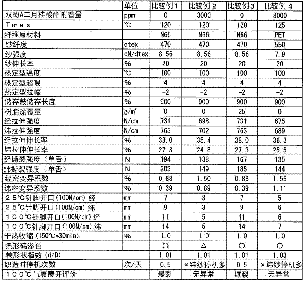
[0064] Polyamide 6·6 resin was melt-spun at 300°C, and while cooling, 0.8% of spinning oil containing 20% bisphenol A dilaurate was applied to the yarn weight, and then drawn with heat at 200°C. The drawing roll stretched to 4.9 times, and after interlacing was applied with compressed air, a raw yarn with a fineness of 470 dtex and a number of filaments of 72 was obtained. The tenacity of the raw yarn was 8.56 cN / dtex, the elongation at break was 20.0%, and Tmax was 120°C. Using this raw yarn, LWT710 manufactured by TOYOTA INDUSTRIES CORPORATION. was used without gluing, with a weaving width of 2.3m, a warp density of 49.5, a weft density of 50, a fabric width of 230cm, and a warp tension of 0.3g / dtex. Plain weaving was carried out at a rotational speed of 600 rpm. The weft insertion device was of a type inserted only by free flight, and the storage capacity was set to 900% of the weaving width. The two selvage parts use 2 33dtex nylon 66 monofilaments as wrapping yarns, a...
Embodiment 2
[0066] In Example 1, the scouring process was omitted, and only tenter processing was performed. The processing conditions are the same as in Example 1. The residual oil content of the obtained fabric was 0.75% by weight based on the weight of the fabric, and 1500 ppm of bisphenol A dilaurate remained. The same evaluation as in Example 1 was performed on this woven fabric, and the results are shown in Table 1.
Embodiment 3
[0068]When melt-spinning polyamide 6.6 resin, apply 1.2% spinning oil containing 20% bisphenol A dilaurate relative to the yarn weight while cooling, and then draw it with a hot drawing roll at 200°C. Stretch to 4.5 times, and interweave with compressed air to obtain a raw yarn with a fineness of 470 dtex and a number of filaments of 72. The tenacity of the raw yarn was 8.03 cN / dtex, the elongation at break was 30%, and Tmax was 120°C. Weaving and post-processing were carried out in the same manner as in Example 1 using this raw yarn. As a result, the residual oil content of the obtained fabric was 0.25% by weight based on the fabric weight, and 500 ppm of bisphenol A dilaurate remained. The same evaluation as in Example 1 was performed on this woven fabric. The results are described in Table 1.
PUM
| Property | Measurement | Unit |
|---|---|---|
| Strength | aaaaa | aaaaa |
| Fineness | aaaaa | aaaaa |
| Strength | aaaaa | aaaaa |
Abstract
Description
Claims
Application Information
 - R&D
- Intellectual Property
- Life Sciences
- Materials
- Tech Scout
- Unparalleled Data Quality
- Higher Quality Content
- 60% Fewer Hallucinations
Browse by: Latest US Patents, China's latest patents, Technical Efficacy Thesaurus, Application Domain, Technology Topic, Popular Technical Reports.
© 2025 PatSnap. All rights reserved.Legal|Privacy policy|Modern Slavery Act Transparency Statement|Sitemap|About US| Contact US: help@patsnap.com


