Fume purification system and working method thereof

A technology for oil fume purification and working methods, which is applied to chemical instruments and methods, oil fume removal, cleaning methods and appliances, etc. It can solve the problems of low oil fume purification rate, collection electric field failure, time-consuming and labor-intensive costs, etc., to ensure the ionization effect and ensure Purification effect, time-saving, labor-saving and cost-saving effect

Inactive Publication Date: 2015-04-29
冯玉报
View PDF12 Cites 2 Cited by
  • Summary
  • Abstract
  • Description
  • Claims
  • Application Information

AI Technical Summary

Problems solved by technology

The disadvantage is that the gaps between the positive and negative plates that constitute the plate electric field are often small, and dirt is easy to accumulate on the positive and negative plates, resulting in a short circuit between the electric fields of the plates, resulting in the failure of the collection electric field and the failure to collect oil. It needs to be disassembled and cleaned regularly, and ultrasonic cleaning is generally used, which is time-consuming, laborious and costly
Its disadvantage is that in actual use, the front end of the metal rib 10 cannot always be on the central axis of the

Method used


Image

  • Fume purification system and working method thereof
  • Fume purification system and working method thereof
  • Fume purification system and working method thereof

Examples


Example Embodiment

[0037] Example 1

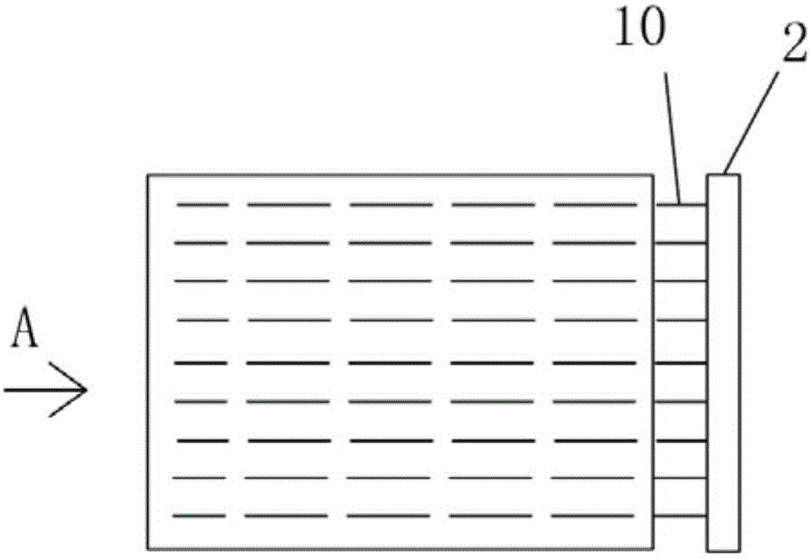
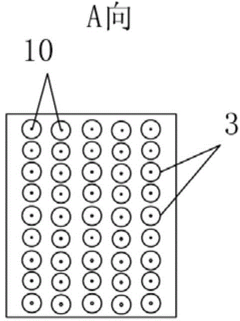
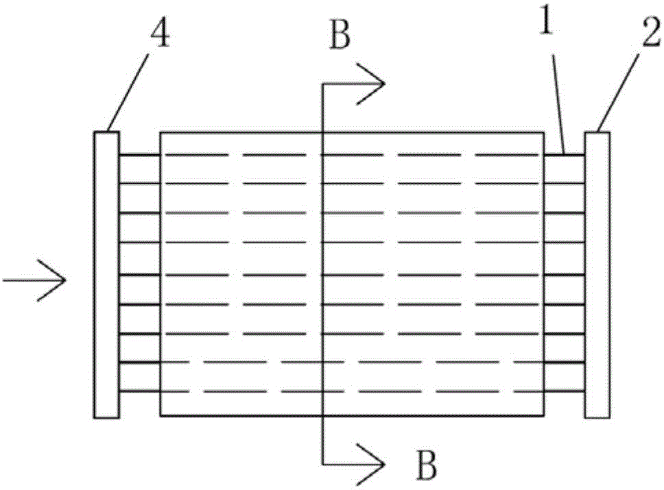
[0038] See Figures 5 to 8 , the oil fume purification system of this embodiment includes: a purification host, the purification host includes: a closed housing 5, the front and rear ends of the housing 5 are respectively provided with an air inlet 15 and an air outlet 16; the housing 5 is provided with a A partition 6, there is a gap between the top of the partition 6 and the inner wall of the housing 5, and the rest of the partition 6 is sealed and welded to the inner wall of the housing 5; inside the housing 5, on both sides of the partition 6 All are provided with a plurality of alternately arranged and vertically distributed metal tubes 13; metal ribs 1 are arranged on the central axis of each metal tube 13, between the middle and upper parts of each adjacent metal tube 13 or adjacent to the top, between the partition plate 6 and Between the upper middle part of adjacent metal pipes 13 or near the top, and the gap between the inner wall of the housing ...

Example Embodiment

[0055] Example 2

[0056] (The upper and lower positions of the three buffer zones in this embodiment are opposite to those in Embodiment 1)

[0057] like Figure 9 , an oil fume purification system, including a purification main engine, the front end of the air inlet 15 of the housing 5 of the purification main engine is also provided with a filter system 17, a cooling system 18 and a buffer cavity 19 for successively filtering, cooling and buffering airflow. The purification host includes: a closed housing 5, the front and rear ends of the housing 5 are respectively provided with inlet and outlet ports 15, 16; There is a gap between the inner walls of the bottom of the partition plate 5, and the remaining part of the partition plate 6 is in sealing connection with the inner wall of the housing 5; inside the housing 5, on both sides of the partition board 6, there are a plurality of alternately arranged and vertically distributed metal Tube 13.

[0058] Metal bars 1 are ar...


PUM

PropertyMeasurementUnit
Diameteraaaaaaaaaa

Abstract

The invention relates to a fume purification system and a working method thereof. A purification host of the fume purification system comprises a closed shell, wherein a partition board is arranged in the shell; a gap is formed between the top of the partition board and the inner wall of the shell, and the other parts of the partition board are in tight coupling with the inner wall of the shell; a plurality of metal tubes are alternately and vertically distributed on two sides of the partition board in the shell; a metal rib is arranged on the central axis in each metal tube, and gaps formed between middle upper parts or the adjacent tops of the every two adjacent metal tubes, between the partition board and the middle upper parts or the adjacent tops of the every two adjacent metal tubes and between the inner wall of the shell and the middle upper parts or the adjacent tops of the every two adjacent metal tubes are closed; a space is formed between the bottom of each metal tube and the inner wall of the bottom of the shell and is divided into a first buffer region and a third buffer region by the partition board; a space is formed between the top of each metal tube and the inner wall of the top of the shell to form a second buffer region; an air inlet and an air outlet of the shell are formed close to the middles or the middle upper parts of the metal tubes located at the front and rear ends.

Description

technical field [0001] The invention relates to an oil fume purification system and a working method thereof, which are applied to printing and dyeing factories (especially the exhaust gas of printing and dyeing setting machines), restaurants and other occasions where the exhaust gas contains oil fumes, plasticizers or other organic compounds. Background technique [0002] The working principle of the electrostatic oil fume purifier is to use a high-voltage electrostatic field to ionize the gas between the electrodes to charge the fine dust and oil mist colloidal particles, so that they can adhere to the plate electrodes to achieve efficient oil fume purification. the goal of. [0003] The dual-zone plate-line electric field in the electrostatic fume purifier includes: an ionization zone composed of a line electric field and an adsorption zone (also called a collection zone) composed of a plate electric field, that is, the ionization zone is composed of several plates connec...

Claims


Application Information

Patent Timeline
IPC IPC(8): B03C3/01B03C3/06B08B3/02B08B3/08F24C15/20
Inventor 冯玉报
Owner 冯玉报
Why Eureka
Try Eureka