
Smoke generator and method of controlling a smoke generation

A smoke generator and generator technology, applied in the direction of artificial fog/smoke devices, ratio control, control/regulation systems, etc., can solve the problems of reducing the possibility of machine performance, blockage, etc., to reduce gas consumption, smoke The effect of low liquid flow and smooth smoke generation

Active Publication Date: 2015-01-14
MARTIN PROFESSIONAL
View PDF5 Cites 16 Cited by
  • Summary
  • Abstract
  • Description
  • Claims
  • Application Information

AI Technical Summary

Problems solved by technology

[0009] It is further seen that existing smoke generators, where gas is normally delivered at relatively high pressure, have problems with clogging in the heat exchanger, which can occur where the required smoke output is reduced to very low levels
To avoid such clogging, the controls of the machine are usually programmed to not allow the smoke output to fall below a certain level, reducing the performance potential of the machine accordingly

Method used


Image

  • Smoke generator and method of controlling a smoke generation
  • Smoke generator and method of controlling a smoke generation
  • Smoke generator and method of controlling a smoke generation

Examples


Embodiment Construction

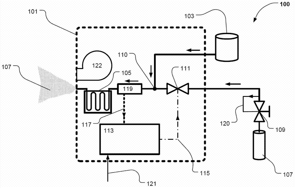
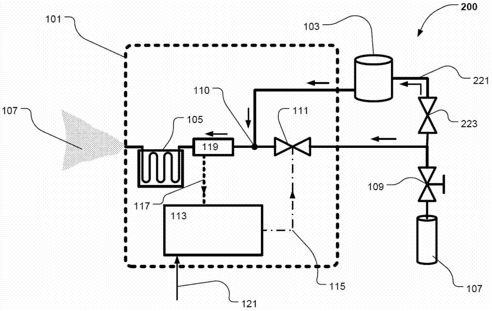
[0052] figure 1 Illustrated is an aerosol generating system 100 comprising an aerosol generator 101 according to an embodiment of the invention connected to a supply of smoke liquid 103 and a supply of pressurized gas 107 . In one embodiment, gas pressure is throttled through a manually operable valve 109 . Such valves can be omitted. Such valve 109 may further include an internal F / B indicating regulator 120 for enhanced safety and control of the pressure level of the supplied gas.

[0053] The flow of smoke liquid and pressurized gas is indicated by arrows.

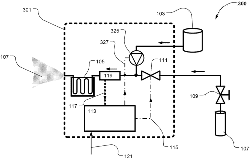
[0054] The smoke liquid 103 is driven to the mixing unit 110 where it mixes with gas. The mixture is directed into the heat exchanger 105 causing the smoke liquid to evaporate and upon exiting the smoke generator 101 to form smoke 107 in contact with the surrounding air. The smoke generator may further include a fan (122) at the smoke outlet, which may be controlled to regulate the flow of smoke from the generator. ...


PUM


Abstract

The invention relates to a method of controlling a smoke generator. The smoke generator is adapted to be connected to a supply of a pressurized gas and a supply of a smoke liquid and further comprises a valve to regulate the pressure of the gas, a fluid driving means, a mixing unit for mixing the smoke liquid and the gas, and a heat exchanger heating the mixture of the pressurized gas and the smoke liquid to vaporize the smoke liquid and form a smoke upon ejection into surrounding air. The control method according to the invention then comprises the steps of receiving a smoke density parameter indicative of a desired amount of smoke to be generated by the smoke generator, measuring a gas pressure at a position between the valve and the heat exchanger, and using these parameters in controlling the valve. The invention further relates to a smoke generator arranged for performing the control method.

Description

technical field [0001] The present invention relates to a method of controlling a smoke generator which drives a mixture of smoke liquid and pressurized gas into a heat exchanger to vaporize the smoke liquid and form smoke when sprayed into the surrounding air. The invention further relates to a smoke generator adapted to implement a control method. Background technique [0002] Smoke generators are used in a variety of applications, such as in security applications to simulate fire as a drill aid, or in the entertainment industry, for example to create on-stage special effects or lighting effects. In the entertainment industry, smoke or mist created by smoke generators is particularly important for smoke effects, but is also critical for creating lighting and lighting effects, some of which, such as aerial beam effects, are only used in conjunction with fine diffuse mist becomes visible. [0003] Smoke generators generally work by driving liquid smoke into a heat exchange...

Claims


Application Information

Patent Timeline
Patent Type & Authority Applications(China)
IPC IPC(8): A63J5/02
CPCG05D11/138A63J5/025F41H9/06G05D11/132A23B4/0526F41H9/08B05B7/1606B05B7/1686B05B12/087
Inventor N.J.斯卡利
Owner MARTIN PROFESSIONAL
Learn More