Digital Manufacturing System For Printing Three-Dimensional Objects On A Rotating Surface

A printing head and inner surface technology, which is applied in processing and manufacturing, manufacturing tools, additive manufacturing, etc., can solve the problems of 3D printer speed limit and other issues

Active Publication Date: 2015-01-14
XEROX CORP
View PDF5 Cites 13 Cited by
  • Summary
  • Abstract
  • Description
  • Claims
  • Application Information

AI Technical Summary

Problems solved by technology

The scanning motion is similar to the way a home inkjet printer operates, and there are strict limits on the speed at which the 3D printer can produce objects

Method used


Image

  • Digital Manufacturing System For Printing Three-Dimensional Objects On A Rotating Surface
  • Digital Manufacturing System For Printing Three-Dimensional Objects On A Rotating Surface
  • Digital Manufacturing System For Printing Three-Dimensional Objects On A Rotating Surface

Examples


Embodiment Construction

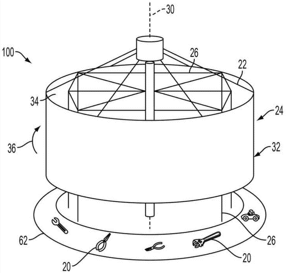
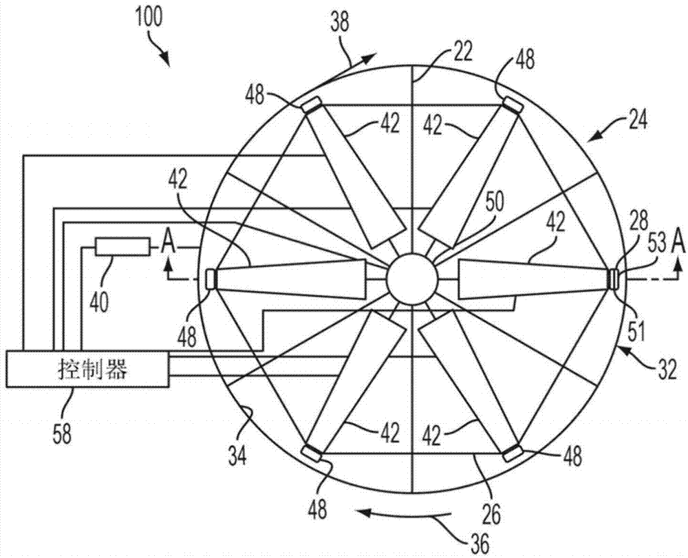
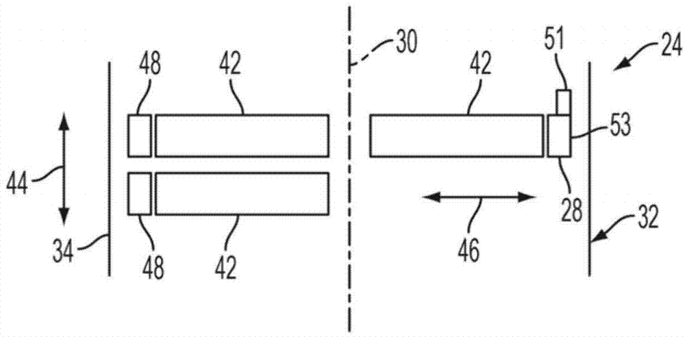
[0014] figure 1 and figure 2 A printer 100 for generating a three-dimensional object 20 is shown. The printer 100 includes an outer frame 22 configured to support a rotatable hollow member 24 and an inner frame 26 configured to hold a first printhead 28 ( figure 2 ) is supported in the hollow part 24. The outer frame 22 is also configured such that the hollow member 24 can rotate about an axis 30 relative to the inner frame 26 . The hollow part 24 has at least one wall 32 forming a continuous inner surface 34 or base material around the axis 30 . Rotation of hollow part 24 about axis 30 (in the direction of arrow 36) causes a portion of inner surface 34 of wall 32 to be along machine direction 38 ( figure 2 ) moves past the first print head 28. The arrangement of the first printhead 28 within the hollow member 24 enables the first printhead 28 to eject material onto the inner surface 34 of the wall 32 in a direction generally away from the axis 30 . As used herein, th...


PUM


Abstract

A printer forms a three-dimensional object on a rotating substrate. The printer includes a first driver to rotate the substrate past at least one printhead at a predetermined velocity and a controller to operate the printhead to eject material onto the substrate to form the object. A second driver is operated to move the position of the printhead perpendicular to the substrate to maintain a predetermined gap between the printhead and the layer of material most distant from the substrate. The second driver is further operable to move the position of the printhead parallel to the substrate to adjust a resolution of the ejected material. The controller interpolates an alternating signal generated from a position encoder to adjust the operation of the printhead based on the rotational position and velocity of the substrate.

Description

technical field [0001] The devices disclosed herein relate generally to three-dimensional printers, and more particularly to devices for producing three-dimensional objects on a moving surface. Background technique [0002] Digital 3D manufacturing (also known as digital additive manufacturing) is the process of manufacturing three-dimensional solid objects of essentially arbitrary shape from digital models. 3D printing is achieved using an additive process that forms successive layers of material on differently shaped substrates. Three-dimensional printing differs from traditional object formation techniques that rely primarily on removing material from a workpiece through a subtractive process such as cutting or drilling. [0003] However, existing 3D systems use production techniques that are slow and generate significant waste. Prior art systems use a flat stage area on which a single scanning printhead slowly deposits layers of material to form an object. The print h...

Claims


Application Information

Patent Timeline
Patent Type & Authority Applications(China)
IPC IPC(8): B29C67/00B22F3/115
CPCB29C67/0059B29C64/112B29C64/153B29C64/40B29C64/393Y02P10/25B41J2/125B41J2/495
Inventor P·J·唐纳森J·J·福克英斯
Owner XEROX CORP
Why Eureka
Try Eureka