Thermoluminescent anti-radiation fabric

A thermoluminescence and radiation protection technology, applied in the field of fabrics, can solve the problems of single function and no radiation protection, and achieve the effect of firm combination, wide application range and strong luminous intensity

Inactive Publication Date: 2015-01-14
WUXI BALAS LIGHTING ELECTRONICS
View PDF0 Cites 0 Cited by
  • Summary
  • Abstract
  • Description
  • Claims
  • Application Information

AI Technical Summary

Problems solved by technology

Ordinary fabrics are single-layer fabrics, and the clothes made of them can only keep warm and cover the body, have a single function,

Method used


Image

  • Thermoluminescent anti-radiation fabric

Examples


Embodiment Construction

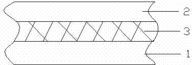
[0014] see figure 1 , the present invention thermoluminescence radiation-proof fabric, it comprises base fabric layer 1 and fabric layer 2, is provided with radiation-proof layer 3 between described base fabric layer 1 and described fabric layer 2, and described radiation-proof layer 3 is metal fibers, the metal fibers are arranged in a network structure.

[0015] The base fabric layer is formed by interweaving warp threads and weft threads, and thermoluminescent crystals are attached to the warp threads and weft threads.


PUM


Abstract

The invention relates to a thermoluminescent anti-radiation fabric. The thermoluminescent anti-radiation fabric comprises a basic fabric layer (1) and a shell fabric layer (2), and is characterized in that an anti-radiation layer (3) is arranged between the basic fabric layer (1) and the shell fabric layer (2); the anti-radiation layer (3) consists of metal fibers and the metal fibers are arrayed in a net-shaped structure; the basic fabric layer is interwoven by warp yarns and weft yarns; and thermoluminescent crystals are attached on the warp yarns and the weft yarns. According to the thermoluminescent anti-radiation fabric, the penetration of electromagnetic radiation can be effectively prevented so that the anti-radiation effect is realized. The thermoluminescent anti-radiation fabric has a wide applicable range.

Description

technical field [0001] The invention relates to a fabric, in particular to a thermoluminescent radiation-proof fabric. Background technique [0002] With the development of science and technology, electronic products are becoming more and more popular, and computers and mobile phones have entered thousands of households, so electromagnetic radiation is also increasing, subtly affecting people's health. Ordinary fabrics are single-layer fabrics, and the clothes made of them can only keep warm and cover the body, have a single function, and have no radiation protection function. In addition, traditional fabrics used to make garments need external light to emit light. Contents of the invention [0003] The object of the present invention is to overcome the above disadvantages and provide a thermoluminescent radiation-proof fabric. [0004] The object of the present invention is achieved in this way: a thermoluminescent radiation-proof fabric, which comprises a base fabric l...

Claims


Application Information

Patent Timeline
IPC IPC(8): B32B15/02B32B5/02B32B33/00
CPCB32B5/02B32B33/00B32B2262/103
Inventor 沈卫军
Owner WUXI BALAS LIGHTING ELECTRONICS
Why Eureka
Try Eureka