While Drilling Inner Canister

A technology of drilling while drilling and inner barrel, which is applied in the field of oil field drilling and workover, and can solve problems such as excessive drilling fluid, depletion of oil production in oil wells, sticking, etc.

Active Publication Date: 2017-02-15
BEIJING AOYIER ENG TECH
View PDF5 Cites 0 Cited by
  • Summary
  • Abstract
  • Description
  • Claims
  • Application Information

AI Technical Summary

Problems solved by technology

[0002] At present, the production layer pressure coefficient of many production oil wells in domestic oilfields is low, and the liquid level is generally between 1000-2000m. The quantity will be exhausted or even discontinued
[0003] Existing sand fishing methods include: circular well washing sand fishing method, sand fishing by suction canister, sand fishing by split giant fishing cup while drilling, etc. The sand fishing method of circular well washing is carried out by pump truck The construction cost of sand washing operation is high. If there is a leakage layer in the upper part of the oil well, other measures must be taken to carry out the construction. Therefore, the operation cost is high, and the well washing fluid will also cause damage to the formation to varying degrees, which is not conducive to the next oil well. Mining; the use of suction-type fishing barrels in the process of sand fishing in the downhole can not be drilled, ground and reamed, and downhole accidents such as sticking are prone to occur; in the process of downhole operations using the split giant fishing cup while drilling, more drilling fluid is consumed , and the sand fishing efficiency is low and the cost is high

Method used


Image

  • While Drilling Inner Canister

Examples


Embodiment Construction

[0017] In order to further illustrate the technical means and functions adopted by the present invention to achieve the predetermined invention goal, the specific implementation of the present invention will be described in detail below in conjunction with the accompanying drawings and preferred embodiments.

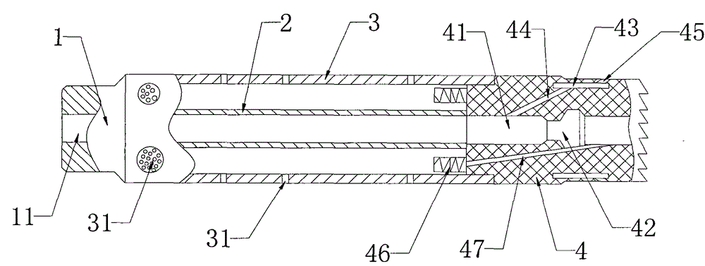
[0018] Such as figure 1 As shown, an inner canister while drilling includes an upper joint 1, an inner cylinder 2, an outer cylinder 3 and a reverse circulation milling shoe 4. The center of the upper joint 1 is provided with a circular channel 11, and the upper joint 1 is screwed on the outer On the top of the cylinder 3, the inner cylinder 2 is set inside the outer cylinder 3 and communicates with the circular channel 11 of the upper joint 1, and the top of the reverse circulation milling shoe 4 is screwed to the bottom of the outer cylinder 3;

[0019] The side wall of the outer cylinder 3 is provided with a plurality of drain holes 31 of different sizes and shapes. T...


PUM


Abstract

The invention discloses a giant while-drilling inner bailing bucket. The giant while-drilling inner bailing bucket comprises an upper connector, an inner bucket, an outer bucket and a reverse circulation mill shoe, the upper connector is connected with the top of the outer bucket, the inner bucket is arranged in the outer bucket, the top of the reverse circulation mill shoe is connected with the bottom of the outer bucket, a through hole is formed in the center of the reverse circulation mill shoe, the top of the through hole is communicated with the bottom of an inner pipe, a ball seat is arranged in the middle of the through hole, the side wall of the reverse circulation mill shoe is provided with a circle of inner overflow cavity, the top end of the inner side of the reverse circulation mill shoe is provided with a plurality of inner overflow inlets, the inner overflow inlets are communicated with the top end of the inner overflow cavity, the bottom end of the outer side of the reverse circulation mill shoe is provided with a plurality of reverse circulation holes communicated with the bottom end of the inner overflow cavity, a check valve is arranged on the edge of the top of the reverse circulation mill shoe, inner circulation holes are formed in the side wall of the reverse circulation mill shoe, the bottoms of the inner circulation holes are communicated with a through hole below the ball seat, and the tops of the inner circulation holes are communicated with the bottom of the check valve. The giant while-drilling inner bailing bucket can reduce the construction cost, protect oil-yielding stratum position, and improve the bailing efficiency.

Description

technical field [0001] The invention relates to the technical field of oil field drilling and workover, in particular to an inner canister while drilling. Background technique [0002] At present, the production layer pressure coefficient of many production oil wells in domestic oilfields is low, and the liquid level is generally between 1000-2000m. The quantity will be exhausted or even discontinued. [0003] Existing sand fishing methods include: circular well washing sand fishing method, sand fishing by suction canister, sand fishing by split giant fishing cup while drilling, etc. The sand fishing method of circular well washing is carried out by pump truck The construction cost of sand washing operation is high. If there is a leakage layer in the upper part of the oil well, other measures must be taken to carry out the construction. Therefore, the operation cost is high, and the well washing fluid will also cause damage to the formation to varying degrees, which is not ...

Claims


Application Information

Patent Timeline
Patent Type & Authority Patents(China)
IPC IPC(8): E21B27/00
CPCE21B27/00
Inventor 练以峰黄世财许兆国
Owner BEIJING AOYIER ENG TECH
Why Eureka
Try Eureka