Method and system for recovering and utilizing flue gas waste heat of regenerative cremation machine

A technology of flue gas waste heat and cremation machine, which is applied in the methods of incinerating corpses, combustion methods, lighting and heating equipment, etc., can solve the problems of site limitation and high energy consumption, achieve convenient disassembly and installation, improve heat conversion rate, and design structure. compact effect

Active Publication Date: 2016-08-31
民政部一零一研究所
View PDF5 Cites 0 Cited by
  • Summary
  • Abstract
  • Description
  • Claims
  • Application Information

AI Technical Summary

Problems solved by technology

[0004] In addition, the problem often encountered in the actual installation and commissioning process is the limitation of the site, and the cremation machine is generally relatively large in size, so it brings many problems, such as: transportation, construction, hoisting, etc. In addition, in the process of cremation The corpse needs to be incinerated at high temperature. In this process, the problem of high energy consumption is involved. With the continuous strengthening of people's awareness of environmental protection, the use of heat energy has become one of the development directions of new cremation machines. In order to solve the above problems, it is urgently needed A new cremation machine system with high heat utilization and easy construction

Method used


Image

  • Method and system for recovering and utilizing flue gas waste heat of regenerative cremation machine
  • Method and system for recovering and utilizing flue gas waste heat of regenerative cremation machine
  • Method and system for recovering and utilizing flue gas waste heat of regenerative cremation machine

Examples


Embodiment Construction

[0060] Below in conjunction with accompanying drawing, the specific embodiment of the present utility model is described further.

[0061] The following examples are only examples for clearly illustrating the utility model, rather than limiting the implementation of the utility model. For those of ordinary skill in the art, on the basis of the following descriptions, other different forms of changes or changes can be made, and these obvious changes or changes that belong to the spirit of the present invention are still protected by the present invention within range.

[0062] An embodiment of a method for recovering and utilizing flue gas waste heat of a regenerative cremator of the present invention is as follows:

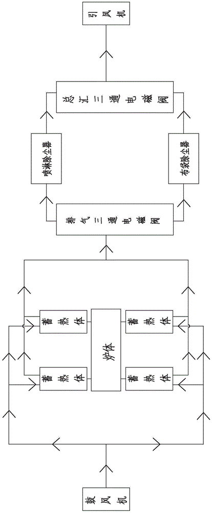
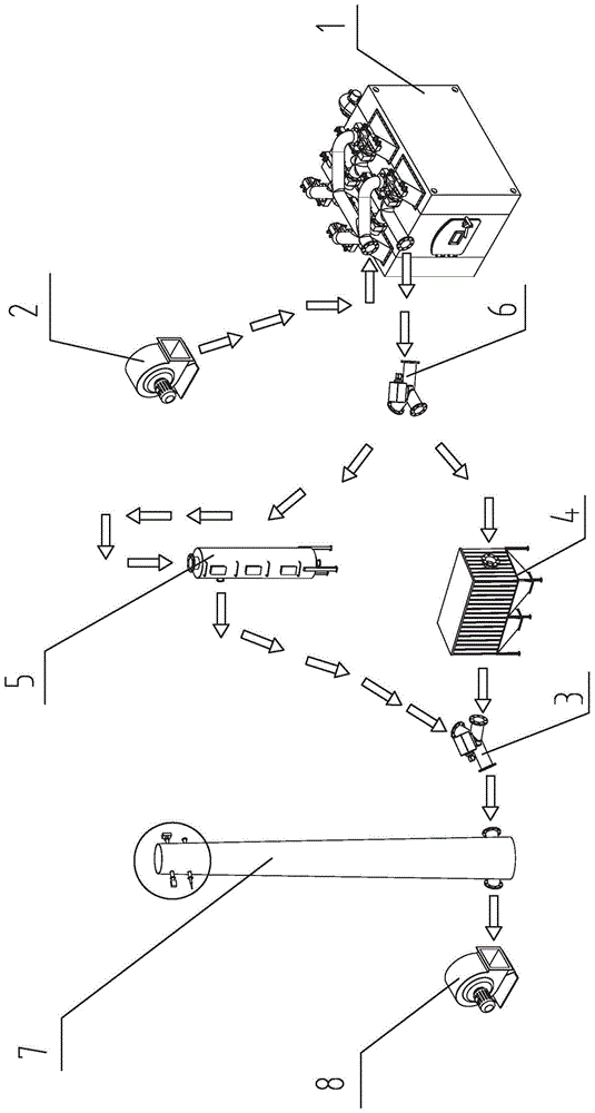
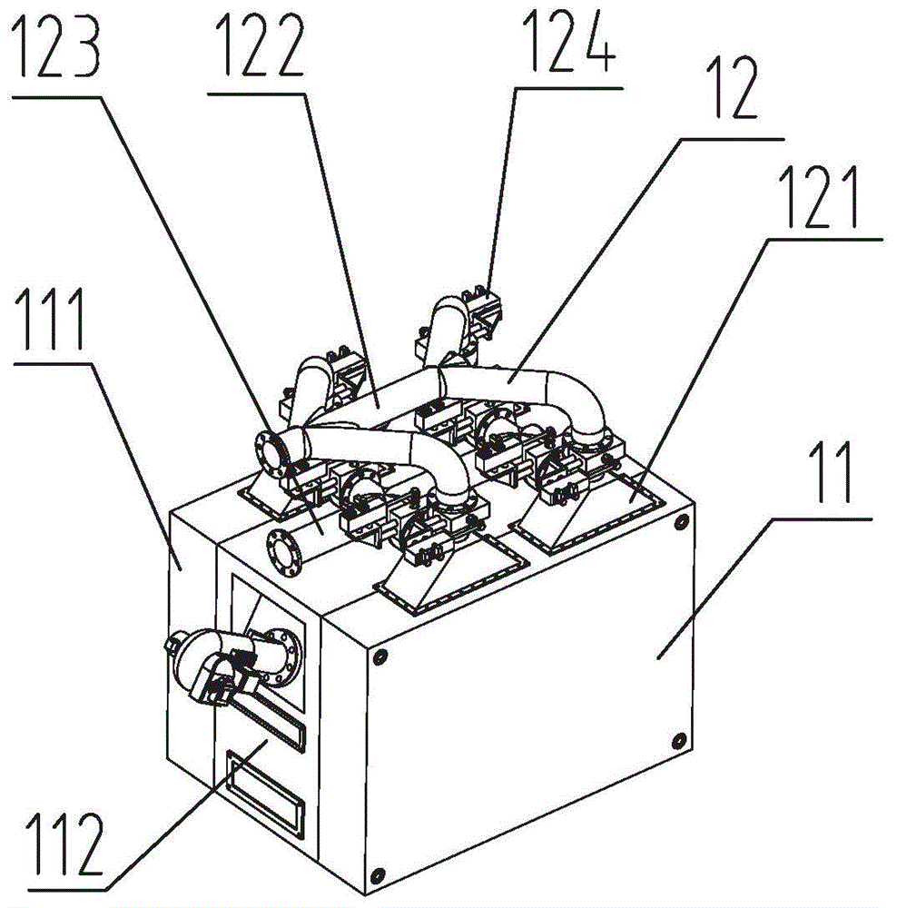
[0063] Such as Figure 1-14 As shown, a method for recovering waste heat from flue gas of a regenerative cremator, the method comprising:

[0064] Step 1, send air or supporting gas into the air intake assembly 122 through the blower 2, the air or supporting ga...


PUM


Abstract

The invention relates to a method for recovering and reutilizing smoke residual heat of a heat storage type cremation machine. The method is characterized in that air or combustion-supporting gas is delivered into an air inlet assembly by a blower, and enters the cremation machine through the air inlet assembly from the top part, residual heat is absorbed by a heat storage body in a heat storage chamber, and then smoke is exhausted out of the top part; the smoke exhausted out of the heat storage chamber enters a main three-way electromagnetic valve through an air exhaust assembly, and selectively enters a bag type dust collector or a spraying type dust collector to be subjected to dust removal according to the main components of the smoke, and the smoke after dust removal is exhausted out by an induced draft fan through a chimney; before exhausting, the components are analyzed. The method has the advantages that by utilizing modularizing design, the cremation machine is favorably detached or installed; the purifying, dust removal and analysis of tail gas are provided, the waste gas is monitored and detected in real time, a smoke system is controlled by a pneumatic butterfly valve, any node can be controlled, and a corpse can be burnt by a high-temperature and oxygen-deficient burning technology; the design structure is compact, and the detachment and installation are convenient.

Description

technical field [0001] The invention relates to a flue gas waste heat recovery method, in particular to a flue gas waste heat recovery method and system for a regenerative cremation machine. Background technique [0002] The incineration of corpses in the funeral industry is the most important work. The cremation machine is one of the most commonly used equipment for incinerating corpses in the funeral industry. It is a special equipment for high-temperature incineration of corpses. , The equipment with low heat utilization, and the traditional cremation machine is not suitable for controlling the combustion gas during the incineration process of the corpse, it simply incinerates the corpse, and the heat utilization rate is low. During this process, a large amount of flue gas will be generated, and the flue gas will be discharged through the chimney, lacking corresponding purification and dust removal and analysis. [0003] In addition, one of the most effective methods for...

Claims


Application Information

Patent Timeline
Patent Type & Authority Patents(China)
IPC IPC(8): F23G1/00F23J15/00
CPCF23G1/00F23J15/006F23J2900/00
Inventor 孟浩李伯森高源郭雷许海峰郭婵史峰方祥田霖
Owner 民政部一零一研究所
Why Eureka
Try Eureka