Parallel flow condenser and air conditioner with same

A condenser and parallel flow technology, which is applied in the direction of evaporator/condenser, refrigerator, refrigeration components, etc., can solve the problems that affect the heat exchange efficiency, and the tube wall is easy to form liquid film or oil film, etc., so as to improve the heat exchange efficiency Effect

Inactive Publication Date: 2015-01-14
HAIER GRP CORP +1
View PDF5 Cites 3 Cited by
  • Summary
  • Abstract
  • Description
  • Claims
  • Application Information

AI Technical Summary

Problems solved by technology

[0004] In order to solve the problem that liquid film or oil film is easily formed on the tube wall of the existing parallel flow condenser, thereby affecting the heat exchange efficiency, the present invention proposes a parallel flow condenser, and its specific technical scheme is as follows:

Method used


Image

  • Parallel flow condenser and air conditioner with same
  • Parallel flow condenser and air conditioner with same
  • Parallel flow condenser and air conditioner with same

Examples


Embodiment 1

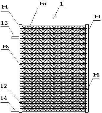
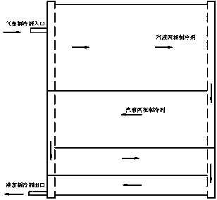
[0022] Embodiment 1, this embodiment proposes a parallel flow condenser 1, including a left header 1-1, a right header 1-1, and several refrigerants connecting the left header and the right header The branch pipe 1-5, the refrigerant branch pipe 1-5 is a flat pipe with a plurality of flow channel holes axially penetrating the flat pipe, and the gaseous refrigerant inlet pipe 1-3 and the gaseous refrigerant The outlet pipe 1-4, the left side header and the right side header 1-1 are respectively provided with spacers 1-2, which divide the internal flow channel of each header into a plurality of sub-flow channel areas, and each sub-flow channel The zone is connected with the corresponding refrigerant branch pipe to change the flow direction of the refrigerant, thereby adjusting the flow of the refrigerant inside the parallel flow condenser.

[0023] The number and arrangement of partitions in each header depends on the refrigerant in different states, preferably 1 to 4, and the i...

Embodiment 2

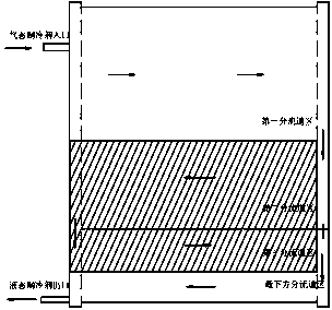
[0031] Embodiment 2. This embodiment proposes an air conditioner, on which the parallel flow condenser described in Embodiment 1 is installed. Part of the liquid refrigerant and compressor oil are introduced into the second half of the condenser by installing the above condenser, thereby greatly improving the heat exchange efficiency in the middle of the parallel flow condenser.


PUM


Abstract

The invention provides a parallel flow condenser. Two sides of the condenser are provided with collecting pipes; the collecting pipes are internally provided with multiple spacers used for separating internal runners of the collecting pipes into multiple sub-runner regions; the spacer behind the first sub-runner region is provided with a leak hole. By use of the characteristic that a liquid refrigerant has specific weight greater than that of press machine oil and is collected toward the bottom of the condenser under the action of gravity, each spacer of each collecting pipe of the parallel flow condenser is additionally provided with a flowing hole, and a part of liquid refrigerant and press machine oil can be guided into the rear half part of the condenser, so that the possibility that the liquid refrigerant or press machine oil is attached to the pipe walls of the collecting pipes is reduced, complete direct contact between a gaseous refrigerant and the pipe walls is ensured, and thus the heat exchange efficiency of the middle of the parallel flow condenser is improved. In addition, the invention also provides an air conditioner.

Description

technical field [0001] The invention relates to a microchannel parallel flow heat exchanger of an air conditioner, which belongs to the improvement technology of the microchannel parallel flow heat exchanger of an air conditioner. Background technique [0002] At present, the heat exchangers of commercially available air conditioners generally have two structures, namely tube-fin heat exchangers and micro-channel parallel flow heat exchangers. As a result, more and more air-conditioning manufacturers pay attention to it and are gradually and widely used in the new generation of air-conditioning products. There are three stages of heat exchange in the microchannel parallel flow condenser: cooling, condensation, and supercooling. The cooling stage is that the gaseous refrigerant is cooled from high temperature to the saturation temperature. The condensation stage is that the refrigerant keeps the saturation temperature unchanged, but the state gradually changes from the gaseou...

Claims


Application Information

Patent Timeline
Patent Type & Authority Applications(China)
IPC IPC(8): F25B39/04
CPCF25B39/04F25B2339/0442
Inventor 张明杰李标张宁宁
Owner HAIER GRP CORP
Why Eureka
Try Eureka