Self-cleaning insulator

A self-cleaning technology for insulators, applied in the direction of insulators, electrical components, circuits, etc., can solve the problems of poor anti-pollution ability of composite insulators, and achieve the effect of saving manpower and material resources and preventing rain flash

Inactive Publication Date: 2015-01-14
STATE GRID CORP OF CHINA +1
View PDF2 Cites 4 Cited by
  • Summary
  • Abstract
  • Description
  • Claims
  • Application Information

AI Technical Summary

Problems solved by technology

[0004] In view of the above problems, the present invention provides a composite insulator with anti-pol

Method used


Image

  • Self-cleaning insulator
  • Self-cleaning insulator
  • Self-cleaning insulator

Examples


Embodiment Construction

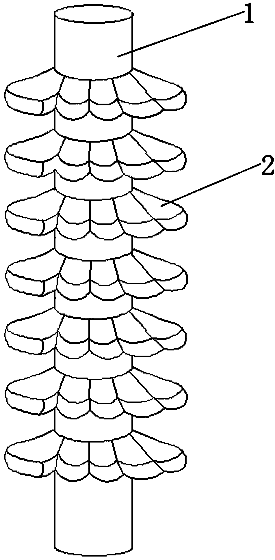
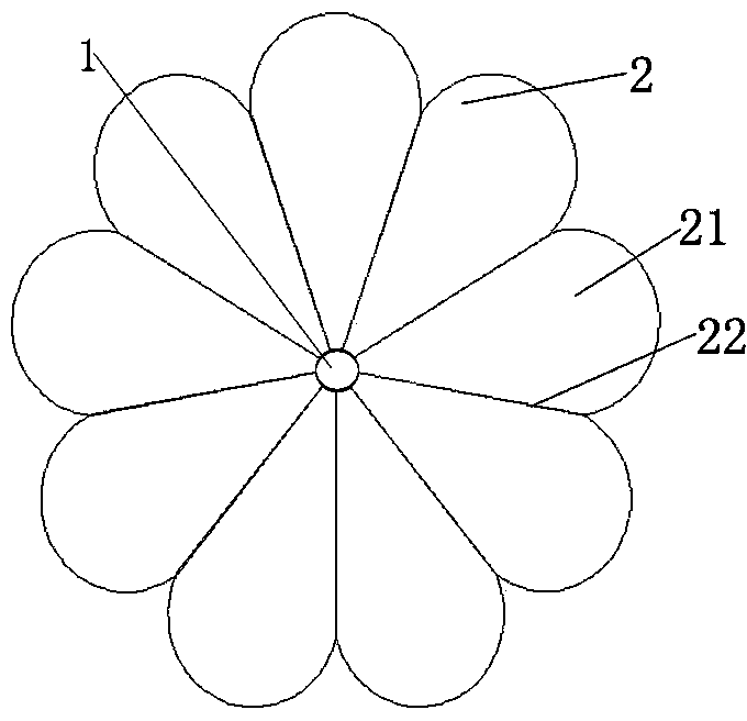
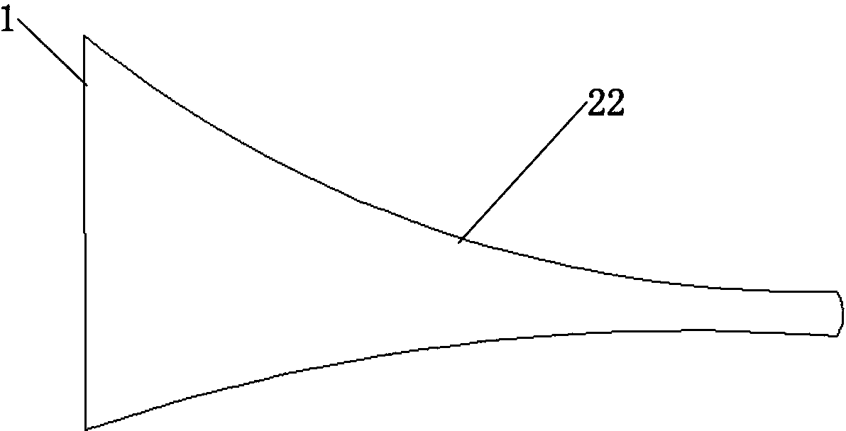
[0013] Such as Figure 1-Figure 4 The insulator designed in the present invention includes an insulator shed 2 and an insulator column 1. The insulator shed 2 is composed of a plurality of sector units 21; the junction of adjacent sector units 21 forms a ridge 22, and the upper surface of the sector unit 21 The height from the insulator column 1 to the edge decreases in order (such as image 3 ), and the cross section of the upper surface of the sector unit 21 is an arc with a high ridge 22 and a concave middle (such as Figure 4 ).

[0014] At least two insulator umbrella skirts 2 may be provided.

[0015] A ridge is formed at the junction of adjacent sector-shaped units adopted by the present invention, the middle of the sector-shaped units is recessed downward, and the center position is higher than the edge position. Because the dust will not accumulate in the spine, it will accumulate in the recessed part. When there is rain, the accumulated dust can be washed away, thus ach...


PUM


Abstract

A self-cleaning insulator comprises insulator umbrella skirts (2) and an insulator column (1) and is characterized in that the insulator umbrella skirts (2) are formed by a plurality of sector-shaped units (21). Ridges (22) are formed at the junction positions of the adjacent sector-shaped units (21), the heights of the upper surfaces of the sector-shaped units (21) are sequentially decreased from the insulator column (1) to the edges, and the cross sections of the upper surfaces of the sector-shaped units (21) are arcs with the high ridges (22) and the concave middles. Compared with the prior art, the ridges are formed at the junction positions of the adjacent sector-shaped units, the middles of the sector-shaped units are sunken downwards, and the central positions are higher than the edge positions. Dust cannot be accumulated at the ridge positions and can be accumulated at the sunken positions, so that when it rains, the accumulated dust can be washed away along with rain, the self-cleaning function is achieved, and manpower and material resources are saved. The rain flows down from the most concave positions at the centers of the sector-shaped units, the rain is unlikely to be connected into a chain shape even during heavy rain or rainstorms, and rain flashover is prevented from being caused.

Description

Technical field [0001] The invention relates to a power transmission equipment, in particular to a self-cleaning insulator. Background technique [0002] There are many edge cleaning devices, most of which are manually cleaned with external tools, but this method requires time and effort. [0003] The slopes of the upper and lower surfaces of the sheds of composite insulators in the prior art are relatively gentle, and their anti-fouling ability is poor. Especially in a dynamic environment, they have poor fouling characteristics and cannot effectively ensure the cleanliness of the product surface. This can cause pollution flashovers, especially when operating safely under high wind speeds. The denser umbrella skirt structure design is easy to chain in heavy rain or heavy rain, causing rain flashes. Summary of the invention [0004] In view of the above problems, the present invention provides a composite insulator with an anti-fouling umbrella skirt to solve the problem of ...

Claims


Application Information

Patent Timeline
IPC IPC(8): H01B17/52H01B17/42
Inventor 裴启刚王接旭粱锋伟刘会霞郑丽娜王源铄
Owner STATE GRID CORP OF CHINA
Why Eureka
Try Eureka