Air-cooled power battery heat management device for electric vehicle and control system

A power battery and air-cooled technology, which is applied in the field of electric vehicle air-cooled power battery thermal management devices and control systems, can solve the problems of difficult power battery cooling, power battery heat dissipation, and no preheating function

Active Publication Date: 2015-01-14
陈言平
View PDF5 Cites 16 Cited by
  • Summary
  • Abstract
  • Description
  • Claims
  • Application Information

AI Technical Summary

Problems solved by technology

The solution of the air-cooled thermal management device is also relatively simple, and more consideration is given to the heat dissipation of the power battery, but there is a blank in the preheating function of the power battery when it is cold started.
[0003] The existing technology has the following problems: (1) The way of forced convection cooling, because no ventilation duct is designed, the effect of cooling and heat dissipation on the power battery close to the electronic fan is more significant, but it will be difficult to effectively cool down and heat the power battery far away from the electronic fan , which will lead to uneven internal temperature of each power battery unit in the battery box, and the natural convection cooling method cannot efficiently dissipate heat for the power battery; It will have a serious impact on the service life of the power battery

Method used


Image

  • Air-cooled power battery heat management device for electric vehicle and control system
  • Air-cooled power battery heat management device for electric vehicle and control system
  • Air-cooled power battery heat management device for electric vehicle and control system

Examples


Embodiment Construction

[0025] The specific implementation manners of the present invention will be further described in detail below in conjunction with the accompanying drawings and embodiments. The following examples are used to illustrate the present invention, but are not intended to limit the scope of the present invention.

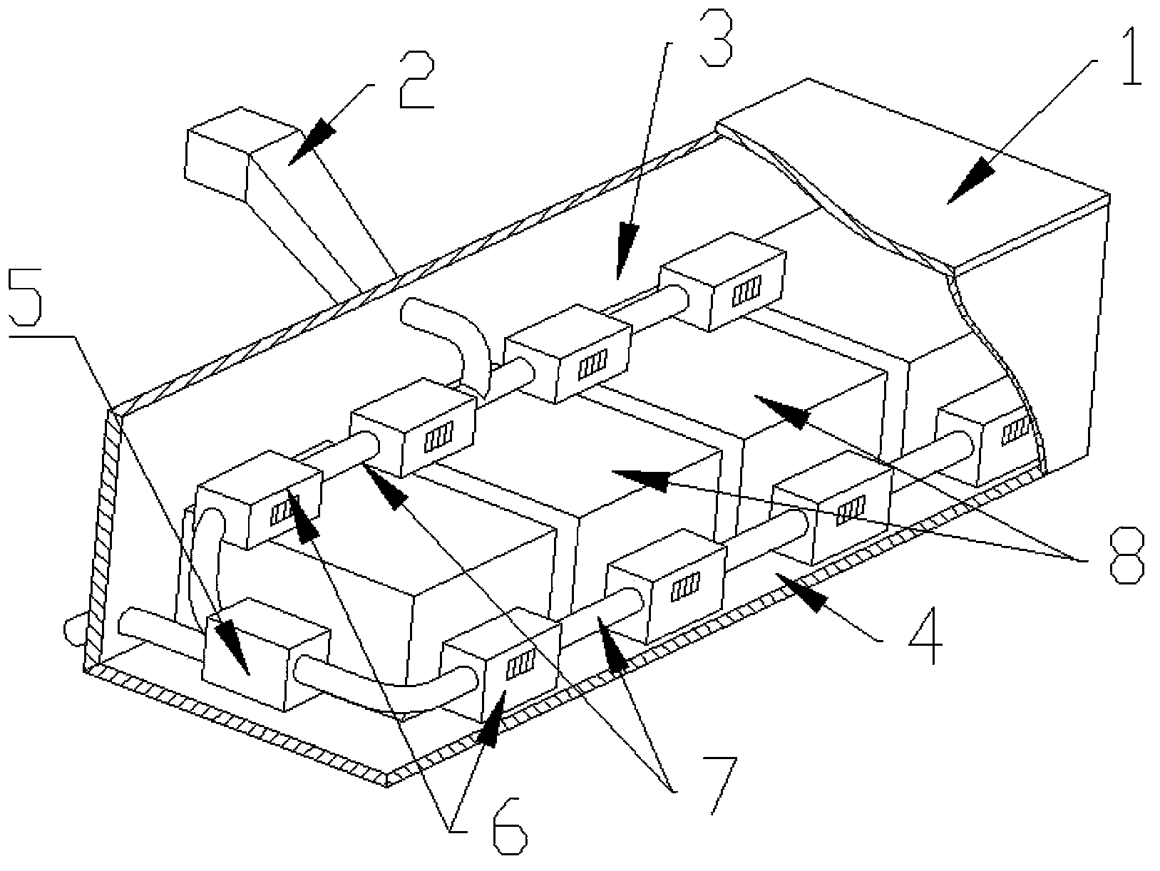
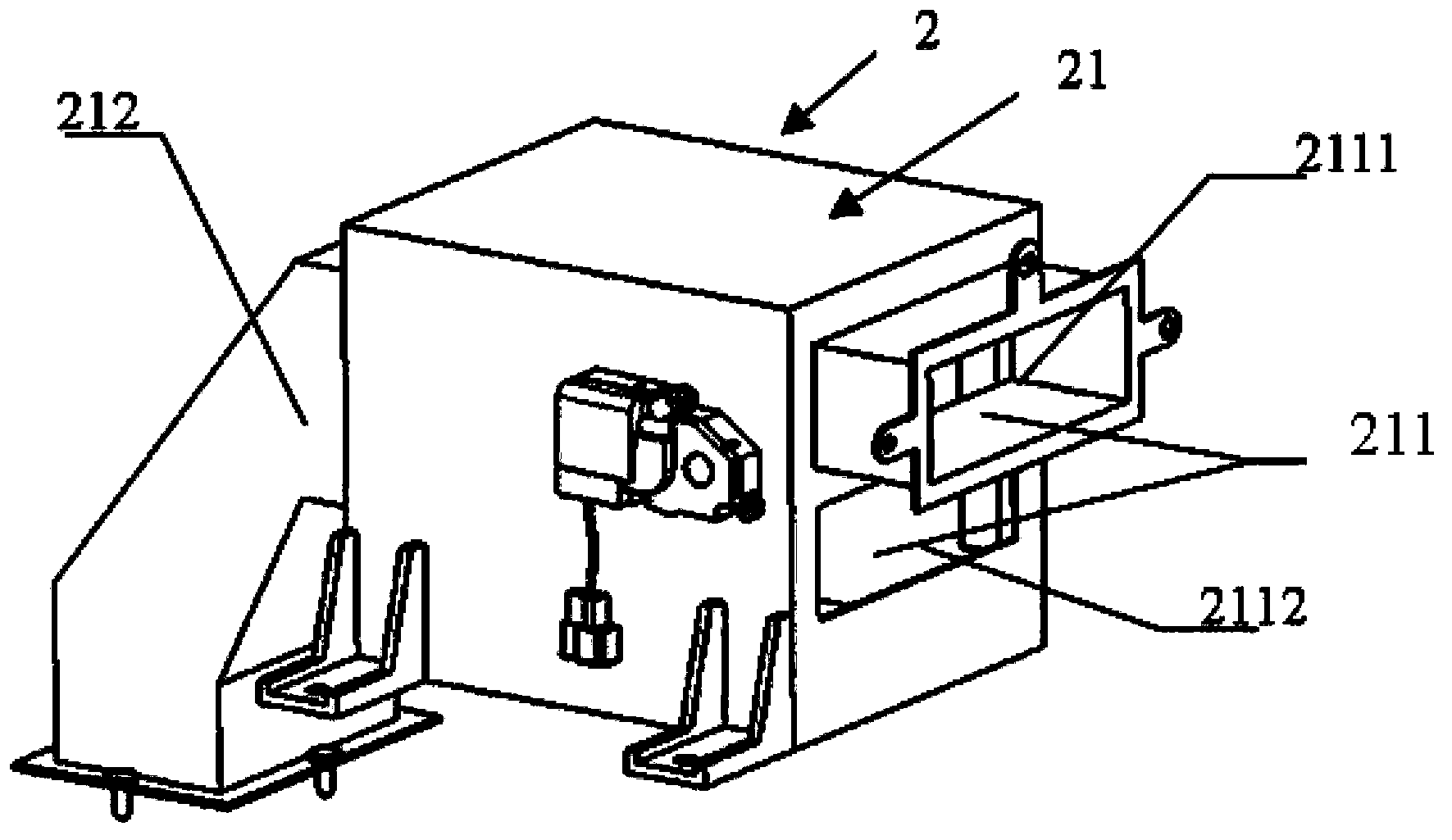
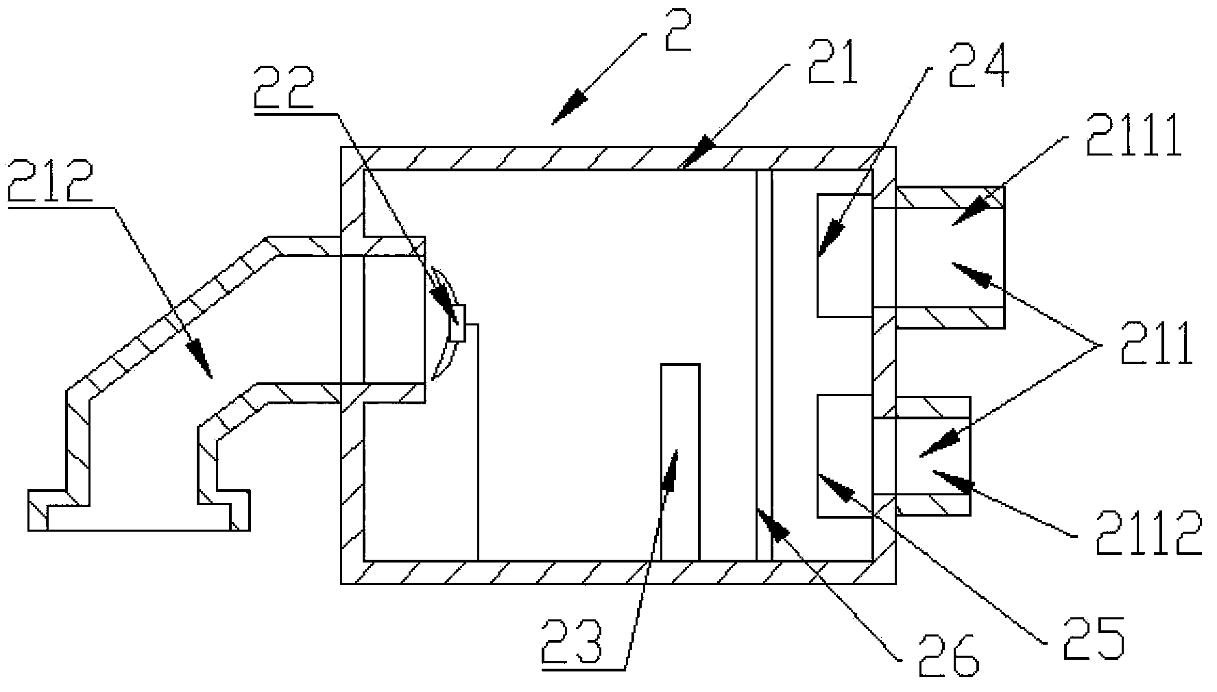
[0026] Such as Figures 1 to 5 As shown, the electric vehicle air-cooled power battery thermal management device of the present invention includes: a battery box 1, an air inlet assembly 2, an air outlet ventilation group 3, a circulation ventilation group 4 and a circulation assembly 5; the power battery 8 is installed in In the battery box 1; the air outlet ventilation group 3 is set in parallel with the power battery 8 in the battery box 1; the circulation ventilation group 4 is arranged in the battery box 1 away from the air outlet ventilation group 3; the air outlet ventilation group 3 and the circulation ventilation group 4 The ventilation boxes 6 are respectively f...


PUM


Abstract

The invention relates to the field of electric automobiles and discloses an air-cooled power battery heat management device for an electric vehicle. The air-cooled power battery heat management device comprises a battery box for mounting a power battery, an air outlet ventilating group and a cycle ventilating group which are formed by connecting multiple ventilating boxes through pipelines, and an air inlet assembly and a cycle assembly, wherein the air outlet ventilating group is arranged in the battery box and is connected with the power battery in parallel; the cycle ventilating group is arranged at a position, which is far away from the air outlet ventilating group, in the battery box; the air inlet assembly absorbs air outside the battery box and blows air into the battery box through the air outlet ventilating group; the cycle assembly absorbs the air in the battery box through the cycle ventilating group, and the air is discharged out of the battery box. The air quantity and air speed of the air flowing in the battery box are uniform, and the problem of non-uniform cooling existing in a forced convection cooling mode in the prior art is solved. Furthermore, a heater is arranged in the cycle assembly, so that the power battery is preheated. The invention also provides a special control system. According to the control system, the power battery can be maintained to operate under optimal operating temperature conditions.

Description

technical field [0001] The invention relates to the field of electric vehicles, in particular to an electric vehicle air-cooled power battery thermal management device and a control system. Background technique [0002] At present, domestic electric vehicle power battery thermal management systems are generally divided into air-cooled and water-cooled. At present, there are two common air-cooling methods for power battery cooling. One is to use natural convection cooling to dissipate power battery cooling; the other is to use electronic fan forced convection cooling to dissipate heat. The solution of the air-cooled thermal management device is also relatively simple, and more consideration is given to the heat dissipation of the power battery, but there is a blank in the preheating function of the power battery when it is cold started. [0003] The existing technology has the following problems: (1) The way of forced convection cooling, because no ventilation duct is design...

Claims


Application Information

Patent Timeline
Patent Type & Authority Applications(China)
IPC IPC(8): H01M10/613H01M10/625H01M10/6561
CPCY02E60/10
Inventor 陈言平
Owner 陈言平
Why Eureka
Try Eureka