Computer optometry unit

A refractometer and computer technology, applied in the field of computer refractor, can solve the problems of complex operation, low efficiency and high labor cost, and achieve the effects of high optometry efficiency, high degree of automation, and improved efficiency and accuracy

Inactive Publication Date: 2015-01-21
HENAN ANNAIDE ELECTRIC POWER EQUIP
View PDF0 Cites 5 Cited by
  • Summary
  • Abstract
  • Description
  • Claims
  • Application Information

AI Technical Summary

Problems solved by technology

Existing computer optometry requires a professional optometrist to perform the optometry. The operation is complicated, the labor cost is high, and the efficiency is low. At the same time, it has certain requirements for the experience of the optometrist.

Method used


Image

  • Computer optometry unit

Examples


Embodiment Construction

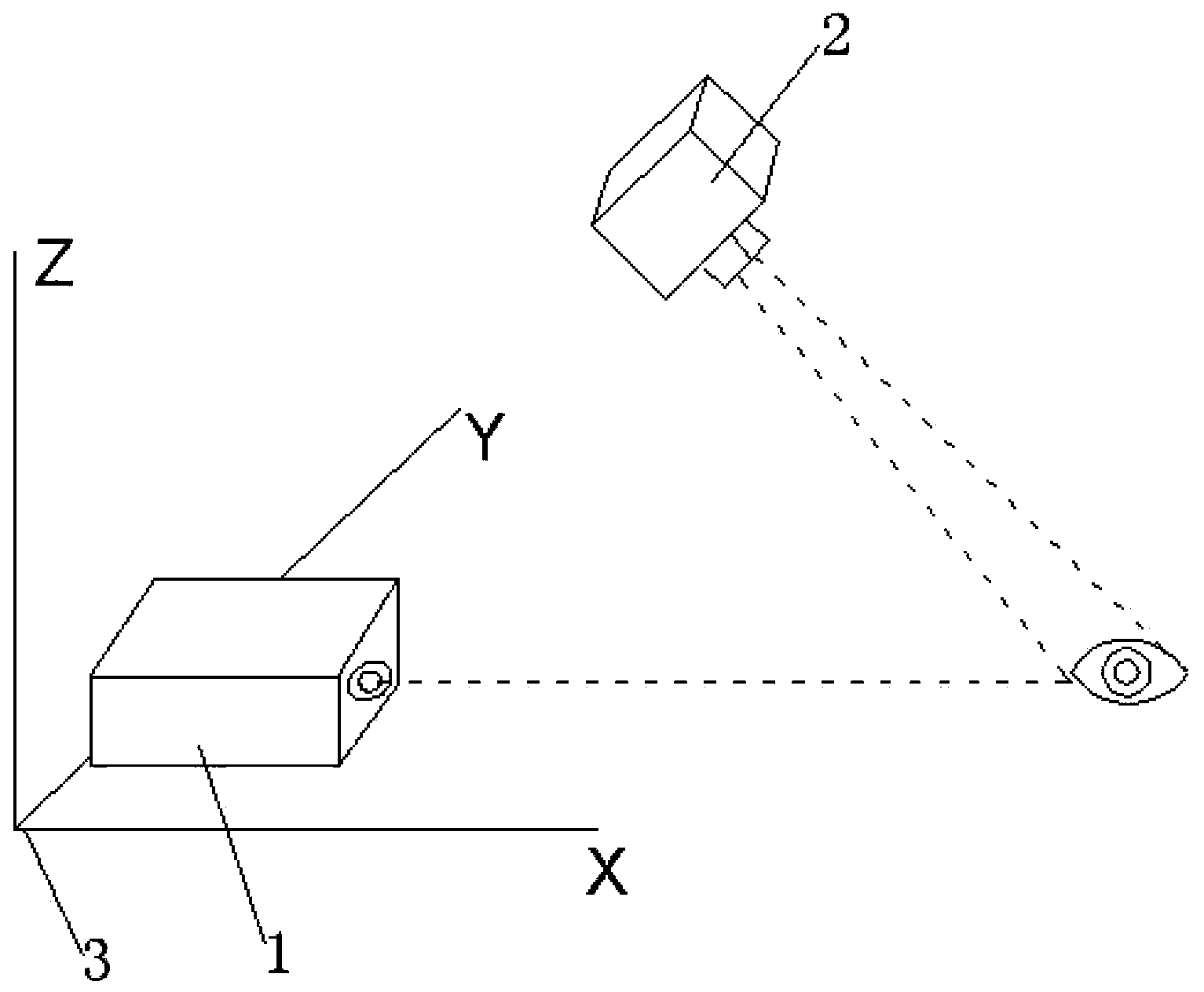
[0007] The present invention will be further explained below in conjunction with the accompanying drawings and specific embodiments. It should be understood that the following specific embodiments are only used to illustrate the present invention and are not intended to limit the scope of the present invention. It should be noted that the words "front", "rear", "left", "right", "upper" and "lower" used in the following description refer to the directions in the drawings, and the words "inner" and "outer ” refer to directions towards or away from the geometric center of a particular part, respectively.

[0008] Such as figure 1 As shown, the computer optometry disclosed in the present invention includes a workbench, a main control computer, a base, and a bracket connected to the workbench and the base. It is characterized in that: the computer optometry also includes a visible light camera, an infrared optometry The visible light camera, the infrared optometry instrument and t...


PUM


Abstract

A computer optometry unit comprises a workbench, a master control computer, a base and a support connected to the workbench and the base. The computer optometry unit further comprises a visible light video camera, an infrared optometry unit and a transmission device provided with a motor. The visible light video camera is movably arranged on the support, and the visible light video camera, the infrared optometry unit and the motor are connected with the master control computer. The optical axis of a lens of the infrared optometry unit and the optical axis of a lens of the visible light video camera are located on the same vertical plane. The computer optometry unit further comprises a pressure switch arranged in the center of the upper surface of the workbench and connected with the master control computer. The computer optometry unit is high in automation degree, optometry repeatability and effectiveness, capable of greatly saving optometry labor cost and optometry time, and high in precision.

Description

technical field [0001] The invention relates to an ophthalmic medical detection device, in particular to a computer optometry instrument. Background technique [0002] At present, there are many optometry equipment on the market, such as comprehensive optometry instrument, automatic optometry instrument, etc. In the optometry process, optometry instrument is an objective optometry instrument, which emits a beam of infrared light of a specific wavelength through the cornea, The lens, aqueous humor, retina and other eyeball organs are finally projected to the eyeball retina, and then reflected back to the corresponding optical system of the instrument, and then received by the CCD, which converts the optical signal into an electrical signal, and decomposes the spherical lens, cylindrical lens and axial position, etc. The data can be used to obtain parameters such as the diopter of the eye to be inspected. Existing computer optometry requires a professional optometrist to perf...

Claims


Application Information

Patent Timeline
Patent Type & Authority Applications(China)
IPC IPC(8): A61B3/103
Inventor 高彦卿李冠峰齐文雅
Owner HENAN ANNAIDE ELECTRIC POWER EQUIP
Why Eureka
Try Eureka