Tilting iron adjusting device in vertical lathe rotation sliding seat

A vertical lathe and adjustment device technology, which is applied in auxiliary devices, turning equipment, accessories of tool holders, etc., can solve problems such as the influence of the running accuracy of the ram and the reduction of product processing quality.

Inactive Publication Date: 2015-01-21
RONGCHENG METAL FORMING MACHINE GROUP
View PDF0 Cites 0 Cited by
  • Summary
  • Abstract
  • Description
  • Claims
  • Application Information

AI Technical Summary

Problems solved by technology

[0003] as attached figure 1 As shown, there is an inclined iron 3 between the ram 1 and the rotary slide 2 of the vertical lathe, and the contact surface between the inclined iron 3 and the ram 1 forms a friction guide rail pair. The ground reciprocates up and down. After long-term wear and tear, there will be a gap between the contact surface of the inclined iron 3 and the ram 1. As the gap continues to increase, the running accuracy of the ram will be affected and the processing quality of the product will be reduced.

Method used


Image

  • Tilting iron adjusting device in vertical lathe rotation sliding seat
  • Tilting iron adjusting device in vertical lathe rotation sliding seat

Examples


Embodiment Construction

[0011] The present invention will be further described below in conjunction with the accompanying drawings and embodiments.

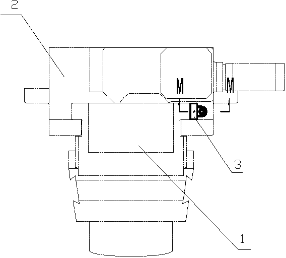
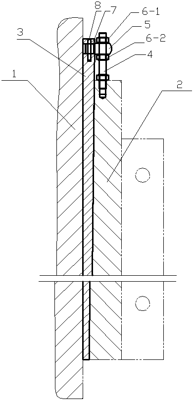
[0012] as attached figure 1 and attached figure 2 As shown, the tilting iron adjustment device in the rotary slide of a vertical lathe includes a rotary slide 2, a ram 1 and a tilting iron 3 between the rotary slide and the ram.

[0013] as attached figure 2 As shown, an adjusting bolt 4 is fixed on the top of the rotary slide 2, and the bottom end of the adjusting bolt 4 extends into the inside of the rotary slide and is fixed by a hexagonal nut to avoid axial movement. Certainly also the bottom end of the adjusting nut 4 can be directly welded to the top of the rotary slide seat 2, but its disassembly is relatively cumbersome after the adjusting nut is damaged.

[0014] as attached figure 2 As shown, the adjustment bolt 4 is provided with a support sleeve 5, and the top and bottom adjustment bolt bolt bodies of the support sleeve 5 are respecti...


PUM


Abstract

The invention belongs to the technical field of lathe machining and aims at providing a tilting iron adjusting device in a vertical lathe rotation sliding seat. The tilting iron adjusting device comprises a rotation sliding seat body, a ram and a piece of tilting iron located between the rotation sliding seat body and the ram, and is characterized in that an adjusting bolt is fixed to the top of the rotation sliding seat body, a supporting sleeve is arranged on the adjusting bolt, an upper adjusting nut and a lower adjusting nut are arranged on the adjusting bolt bodies at the top and the bottom of the supporting sleeve respectively, and the supporting sleeve is clamped by the upper adjusting nut and the lower adjusting nut and fixedly connected with the tilting iron. The tilting iron adjusting device is simple in structure, convenient to operate and capable of effectively improving the machining accuracy of a lathe.

Description

[0001] technical field [0002] The invention belongs to the technical field of lathe processing, and specifically refers to an oblique body adjustment device in a rotary slide seat of a vertical lathe. Background technique [0003] as attached figure 1 As shown, there is an inclined iron 3 between the ram 1 and the rotary slide 2 of the vertical lathe, and the contact surface between the inclined iron 3 and the ram 1 forms a friction guide rail pair. The ground reciprocates up and down. After long-term wear and tear, there will be a gap between the contact surface of the inclined iron 3 and the ram 1. As the gap continues to increase, the running accuracy of the ram will be affected and the processing quality of the product will be reduced. Contents of the invention [0004] The purpose of the present invention is to provide a tilting iron adjustment device in the rotary slide seat of a vertical lathe, which can timely eliminate the gap error between the tilting iron and...

Claims


Application Information

Patent Timeline
Patent Type & Authority Applications(China)
IPC IPC(8): B23Q1/00
CPCB23B25/00
Inventor 张雷芮珍珍孟繁营王贺
Owner RONGCHENG METAL FORMING MACHINE GROUP
Why Eureka
Try Eureka