A foundation pit support structure

A technology of foundation pit support and support rods, which is applied in the direction of foundation structure engineering, excavation, construction, etc., can solve the problems of flat support occupying the space in the pit, long construction period, and increased project cost, so as to achieve convenient installation and disassembly and low production cost. Low, eliminate the effect of welding

Active Publication Date: 2016-01-27
杭州爱默乐实验设备有限公司
View PDF7 Cites 3 Cited by
  • Summary
  • Abstract
  • Description
  • Claims
  • Application Information

AI Technical Summary

Problems solved by technology

[0003] Flat braces are currently widely used in deep foundation pits, but flat braces take up a lot of space in the pit, and the construction period is long, which is not conducive to excavation operations. There are great safety hazards in later demolition, which not only increases the cost of the project, but also is not conducive to environmental protection.
Reverse anchoring technology is a new technology popularized in recent years. The advantage of reverse anchoring is that the foundation pit is open and open, which is convenient for excavation and structure construction, but it is prone to group anchor effect, small safety factor and poor stability. The construction process is cumbersome and the cycle is long. Anchorage beyond the red line of land use cannot make full use of land resources
[0004] Diagonal braces are mostly used in the central island construction of super-large foundation pits. Compared with flat braces, they have more economic advantages, but they need to be excavated in the center of the foundation pit first during construction. Construction joints must be reserved during construction, the procedures are cumbersome and the construction period is long, and later demolition and structural processing are difficult
[0005] Traditional foundation pit support includes base plate, support base, support rod, support frame, rectangular tube and guard plate. Since the position of the guard plate and rectangular tube is uncertain, in order to ensure the stability of the support, the support base connected by the support rod and Under normal circumstances, the support frame needs to be welded one by one on site, which consumes huge financial and material resources. With the increasing area and depth of foundation pit excavation, it is difficult for the traditional support system to meet the role of safety and economy. The structural firmness and stability of the form are poor, and the installation and dismantling are more troublesome, the amount of work is large, the cost is high, and the construction period is long

Method used


Image

  • A foundation pit support structure
  • A foundation pit support structure
  • A foundation pit support structure

Examples


Embodiment Construction

[0016] The specific implementation manner of the present invention will be described in detail below in conjunction with the accompanying drawings.

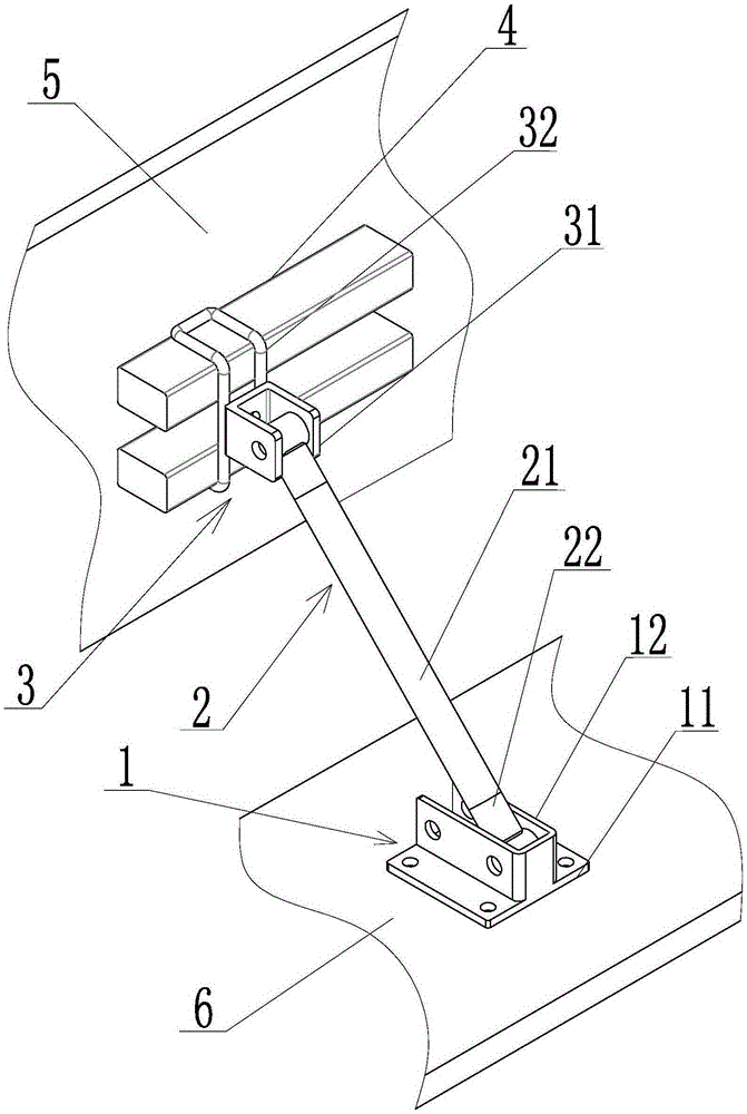
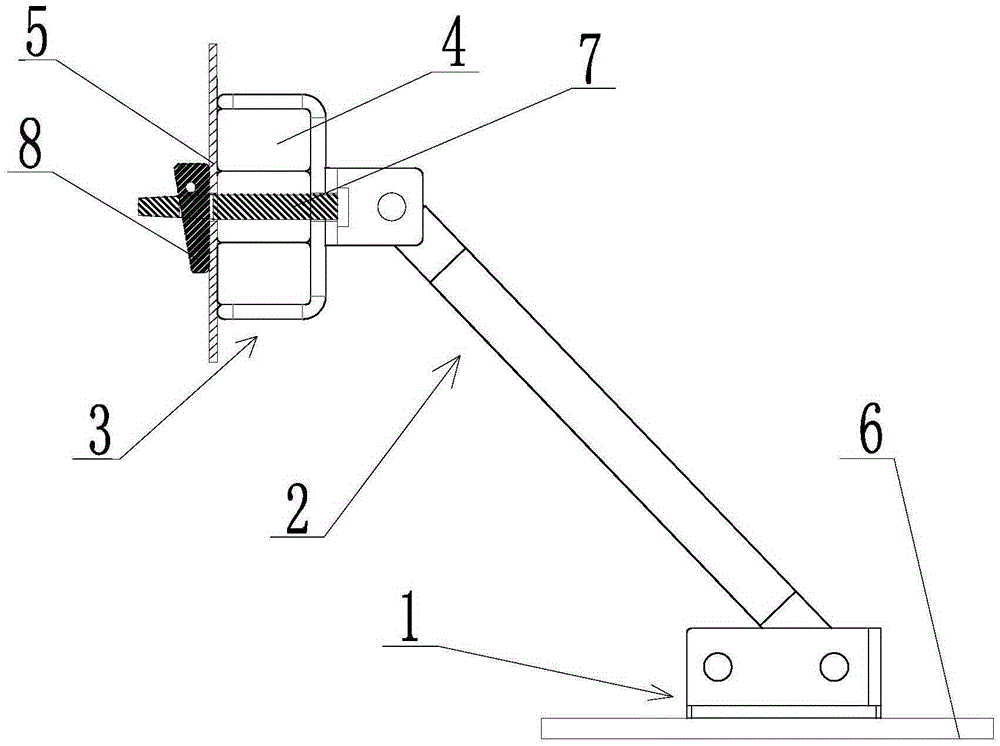
[0017] Such as figure 1 , figure 2 , image 3 , Figure 4 with Figure 5 The shown foundation pit support structure includes a bottom plate 6, a support base 1, a support rod 2, a support frame 3, a rectangular tube 4 and a guard plate 5, and the support base 1 includes a base plate 11 and a first connecting block 12 , the first connecting block 12 is bent into a U-shape by a steel plate, and the U-shaped end face on one side is welded to the base plate 11 .

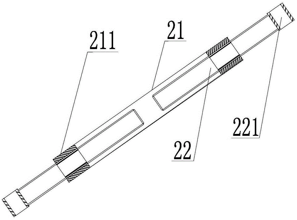
[0018] The support rod 2 includes a rod cover 21 and a telescopic screw 22, the inner walls of the two ends of the rod cover 21 are provided with threads 211, and the two telescopic screws 22 are respectively screwed into the two ends of the rod cover 21, and the telescopic rod 22 is exposed. One end of cover 21 is also provided with a section of circular pipe 221, th...


PUM


Abstract

The invention relates to a supporting structure of a foundation pit. The supporting structure comprises a base plate, a supporting base, a supporting rod, a supporting frame, rectangular pipes and a protection plate. The supporting frame comprises a bracket and a second connecting block, the second connecting block is formed by bending a steel plate into a U shape. The whole bracket is formed by bending round steel to be of a U-shaped frame structure, the bracket comprises connecting portions and locating portions, the connecting portions are two pieces of straight round steel welded to the bottom of the second U-shaped connecting block in a spaced mode, the two pieces of straight round steel are parallel to the two side walls of the second U-shaped connecting block respectively, the two locating portions are U-shaped round steel, and the two open ends of the locating portions are fixedly connected with the same ends of the two pieces of straight round steel respectively. The two rectangular pipes are welded to one side of the protection plate in parallel in a spaced mode, the inner sides of the locating portions of the bracket are attached to the two rectangular pipes respectively, a pin penetrates through the bottom of the second connecting block and the protection plate, and a pin sheet is inserted into the end, close to the protection plate, of the pin to fix the bracket and the protection plate. The supporting structure is simple, mounting is convenient, and a large amount of manpower and a large number of material resources are saved.

Description

technical field [0001] The invention relates to the technical field of civil engineering, in particular to a foundation pit support structure. Background technique [0002] During the excavation of the foundation pit, the surrounding soil will inevitably be deformed, which will affect the surrounding buildings and underground pipelines. Seriously, it will endanger its normal use or safety. In order to avoid this situation, a support system will be added to stabilize the safety of the foundation pit in deep foundation design and pit construction. At present, there are three main forms: flat brace, diagonal brace and reverse anchoring technology . [0003] Flat braces are currently widely used in deep foundation pits, but flat braces take up a lot of space in the pit, and the construction period is long, which is not conducive to excavation operations. There are great safety hazards in later demolition, which not only increases the cost of the project, but also is not conduci...

Claims


Application Information

Patent Timeline
Patent Type & Authority Patents(China)
IPC IPC(8): E02D17/04
CPCE02D17/04E02D2600/20E02D2600/30
Inventor 高尔荣
Owner 杭州爱默乐实验设备有限公司
Why Eureka
Try Eureka