gear pump

A gear pump, driving gear technology, applied in the direction of pumps, pump components, rotary piston pumps, etc., can solve the problems of increased friction, difficult to accurately control the pressing force on the end face of the gear, and increased leakage, so as to reduce the leakage of the end face. , the use of a wide range of effects

Active Publication Date: 2016-08-10
东莞力嘉塑料制品有限公司
View PDF7 Cites 0 Cited by
  • Summary
  • Abstract
  • Description
  • Claims
  • Application Information

AI Technical Summary

Problems solved by technology

Although the leakage can be reduced by using the fixed side plate to reduce the end face clearance, the viscous friction loss will increase, resulting in an increase in power loss; the floating side plate can automatically compensate the gap according to the wear, but the floating side plate has an effect on the end face of the gear. It is difficult to control the pressing force accurately. If the pressing force is too high, the friction force will increase and the power loss will increase. If the pressing force is too small, it will not be able to play the role of end face sealing, and the leakage will increase.
[0005] In addition, in the process of conveying liquid in the existing gear pump, due to the dilution and washing of the liquid, the lubricating grease inside the gear pump is taken away by the liquid, and the lubrication effect will become worse and worse with the operation of the gear pump, and the wear will also increase. getting worse

Method used


Image

  • gear pump
  • gear pump
  • gear pump

Examples


Embodiment Construction

[0030] The present invention will be described in further detail below in conjunction with the examples and the accompanying drawings, but the implementation of the present invention is not limited thereto.

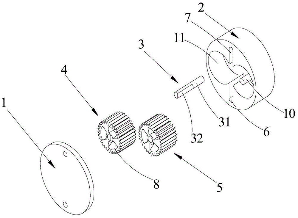
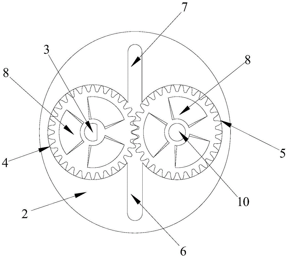
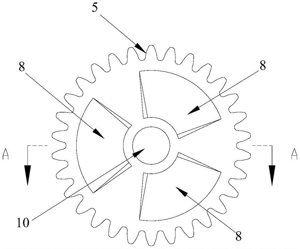
[0031] like Figures 1 to 4 As shown, the gear pump provided by the present invention includes an end cover plate 1, a rear cover 2, a drive shaft 3, and a driving gear 4 and a driven gear 5 that mesh with each other. The driving gear 4 is installed on the drive shaft 3, and the rear cover 2 A fixed shaft 10 is arranged on the top, and the driven gear 5 is installed on the fixed shaft 10. The back cover 2 is also provided with a suction port 6 and a discharge port 7. The back cover 2 cooperates with the end cover plate 1 to form a closed space, and the drive gear 4 and The driven gears 5 are all arranged in the closed space, and at least one end surface of the driving gear 4 and the driven gear 5 is provided with a groove 8, and lubricating grease is stored in the groove ...


PUM


Abstract

The invention belongs to the technical field of pumps, and in particularly relates to a gear pump. The gear pump comprises an end surface cover board, a rear cover, a driving shaft, as well as a driving gear and a driven gear which are meshed with each other, wherein the driving gear is mounted on the driving shaft, a fixed shaft is arranged on the rear cover, the driven gear is mounted on the fixed shaft, a sucking hole and an exhaust hole are formed in the rear cover, the rear cover and the end surface cover board are matched to form closed space, the driving gear and the driven gear are mounted in the closed space, a groove is formed in at least one end surface of the driving gear and / or the driven gear, lubricating grease is stored in the groove. Compared with the prior art, the gear pump has the advantages that the leakage of the end surface is reduced under the condition that the friction loss and power loss are not increased, the gear pump can be well lubricated continuously, and thus the loss of the gear pump is reduced.

Description

technical field [0001] The invention belongs to the technical field of pumps, in particular to a gear pump. Background technique [0002] A pump is a machine that transports liquid or pressurizes the liquid. It transfers the mechanical energy of the prime mover or other external energy to the liquid to increase the energy of the liquid. A gear pump is a commonly used pump, which is a rotary pump that relies on the change and movement of the working volume formed between the pump cylinder and the meshing gear to deliver liquid or pressurize it. [0003] Gear pumps generally have the problem of volume loss. The reasons for volume loss mainly include: radial leakage, end surface leakage, gear meshing point leakage, and elastic loss during liquid compression. Among them, the end surface leakage refers to the gap between the gear end surface and the side plate (end surface cover plate) or the bearing end surface, and the liquid will leak into the suction chamber through these ga...

Claims


Application Information

Patent Timeline
Patent Type & Authority Patents(China)
IPC IPC(8): F04C2/18F04C15/00
Inventor 韩超郭坤叶德全陈汉雄
Owner 东莞力嘉塑料制品有限公司
Why Eureka
Try Eureka