
Discrete magnetic angle sensor device, a magnetic angle sensor arrangement, a method for generating an angle signal and a method for providing a sensor signal

A magnetic angle sensor and magnetic sensor technology, applied in the direction of converting sensor output, measuring devices, and using electrical devices, can solve problems such as high angle errors, and achieve the effects of increasing sensitivity, improving accuracy, and reducing accuracy

Active Publication Date: 2015-01-21
INFINEON TECH AG
View PDF6 Cites 26 Cited by
  • Summary
  • Abstract
  • Description
  • Claims
  • Application Information

AI Technical Summary

Problems solved by technology

[0004] Due to the arrangement of the magnet relative to the magnetic field sensor, the sensor may suffer from non-optimal magnetic field conditions which may result in higher errors in the angle of the magnetic field created by the magnet compared to more conventional designs

Method used


Image

  • Discrete magnetic angle sensor device, a magnetic angle sensor arrangement, a method for generating an angle signal and a method for providing a sensor signal
  • Discrete magnetic angle sensor device, a magnetic angle sensor arrangement, a method for generating an angle signal and a method for providing a sensor signal
  • Discrete magnetic angle sensor device, a magnetic angle sensor arrangement, a method for generating an angle signal and a method for providing a sensor signal

Examples


Embodiment Construction

[0088] Hereinafter, embodiments according to the present invention will be described in more detail. In this context, summarizing reference signs will be used to describe several objects at the same time, or to describe common features, dimensions, characteristics, etc. of these objects. Summarizing reference symbols is based on their respective reference symbols. Furthermore, objects appearing in several embodiments or several figures (but which are identical or at least similar in at least some aspects of their functions or structural features) will be denoted by the same or similar reference symbols. In order to avoid unnecessary repetition, parts of the description referring to such objects also refer to corresponding objects in different embodiments or in different figures, unless stated otherwise explicitly or implicitly considering the context of the specification and figures. Therefore, similar or related objects can be realized with at least some identical or similar...


PUM


Abstract

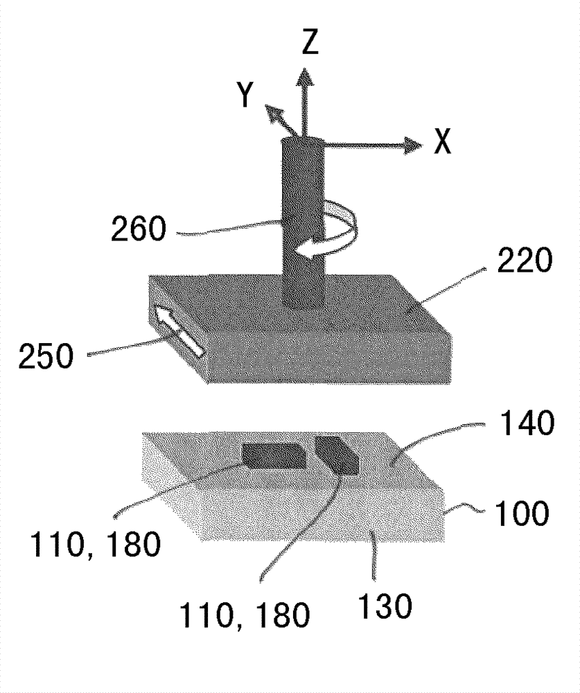
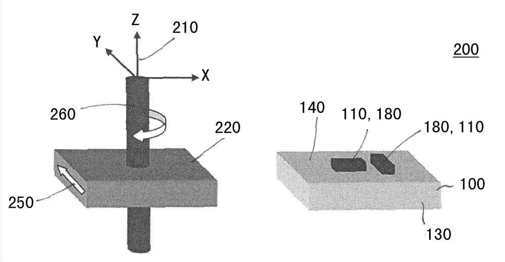
A discrete magnetic angle sensor device according to an embodiment includes a first magnetic field gradiometer and a second magnetic field gradiometer. The first magnetic field gradiometer and the second magnetic field gradiometer are of different types of a group of gradiometer types. An embodiment may improve an accuracy of a determination of a rotation angle.

Description

technical field [0001] Embodiments relate to a discrete magnetic angle sensor arrangement, a magnetic angle sensor arrangement, a method for generating an angle signal and a method for providing a sensor signal, which can be used, for example, to determine a first component relative to a second component, as for example in the field of automotive applications. The rotation angle of the second part. Background technique [0002] In many applications, the first component rotates or pivots relative to the second component. Examples eg come from the field of automotive applications, such as the determination of steering angles. For example, it may be advisable for the control unit of the car to determine the steering angle by measuring the angle of rotation of the steering column. Conventionally, magnets may be mounted magnetized on the end of the corresponding shaft or axis such that a magnetic field sensor arranged along the axis of rotation of the shaft or axis can detect c...

Claims


Application Information

Patent Timeline
Patent Type & Authority Applications(China)
IPC IPC(8): G01B7/30
CPCG01R33/022G01B7/30G01D5/145G01R33/02G01D5/147G01D5/165
Inventor U.奥瑟莱希纳
Owner INFINEON TECH AG
Learn More