
Compression heat generation detector and method

A compression heat generation and detector technology, which is applied to instruments, calorimeters, and the use of stable tension/pressure to test the strength of materials. And other issues

Active Publication Date: 2017-01-25
EVE RUBBER RES INST
View PDF8 Cites 0 Cited by
  • Summary
  • Abstract
  • Description
  • Claims
  • Application Information

AI Technical Summary

Problems solved by technology

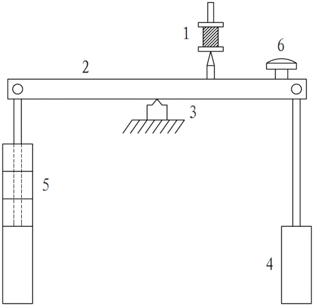
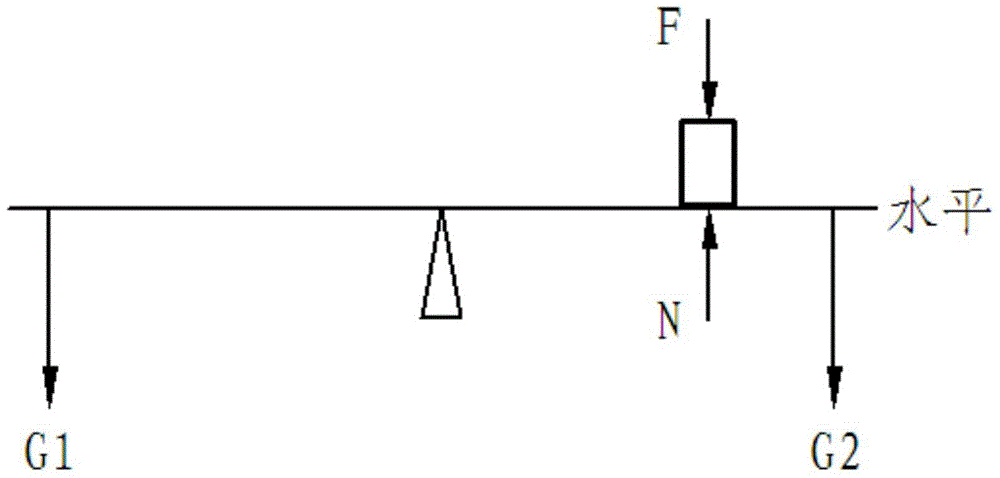
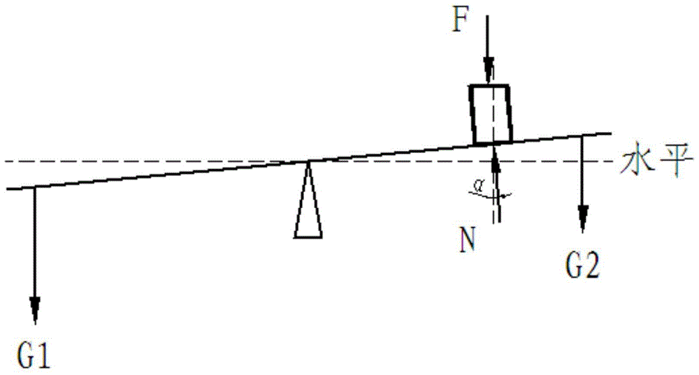
[0007] 1. If image 3 As shown, the balance lever balance compensates the lower surface of the sample. Since the fulcrum of the lever does not coincide with the supporting point of the sample, when the lever tilts at a certain angle α due to the weight difference between the front and rear lumps, the lower surface of the sample and the upper surface under pressure will be caused. The surface is not parallel, and the wheel is subjected to the gravity model of the vehicle body, and the periodic compression of the vehicle body is biased, and the actual working conditions cannot be accurately simulated under the experimental conditions
[0008] 2. The compensation value is inaccurate
[0009] 3. The core temperature cannot be measured in real time
But at this time, when the needle-shaped temperature sensor is inserted into the rubber sample, its temperature is quite different from the real temperature inside the sample, which will cause errors in the test results.
[0010] 4. The instrument can only measure the temperature of one sample
This method has a complex structure, and there is friction between the temperature sensor probe and the rubber sample during the compression process, which will affect the reliability and operability of the equipment and the accuracy of the test results to a certain extent.

Method used


Image

  • Compression heat generation detector and method
  • Compression heat generation detector and method
  • Compression heat generation detector and method

Examples


Embodiment Construction

[0055] specific implementation plan

[0056] The present invention includes one or more sets (optimally two sets) of independently operable detection units, and each independent detection unit includes a set of vertical compressing device, a set of vertical compensating device and a synchronizing device for core core temperature sensor.

[0057] Such as Figure 6 As shown, taking one set of detection units as an example, the vertical compression device and the vertical compensation device are respectively fixed on the top frame 8 . The long guide shaft 17 in the vertical compression device is vertically guided along the corresponding hole in the top frame 8 . The lower bearing box 23 and the upper bearing box 27 of the leading screw in the vertical compensator are fixed on the top frame 8 respectively, and similarly, two short guide shafts 28 are also fixed on the top frame 8 respectively. The core core temperature sensor synchronizing device is installed between the pressin...


PUM


Abstract

A compression heat generation detector and method thereof, comprising one or more sets of detection units, the detection unit includes a vertical compression device, a vertical compensation device and a core core temperature sensor synchronization device; the vertical compression device and the vertical compensation device are respectively Fixed on the top frame, the core core temperature sensor synchronization device is installed on the pressure plate and vertical compensation of the vertical compression device through a transition column with the same or similar mechanical properties as the transition column and a pad with the same or similar mechanical properties as the pressure sensor Between the supporting plates of the device, the transition column just passes through the hole of the middle support, without affecting the accuracy of the pressure sensor for the compression stress test of the rubber sample. The device can perform vertical compression on the test sample, vertical compensation and accurately test the temperature change at the center of the sample during the test, and can accurately simulate the actual working conditions.

Description

technical field [0001] The invention relates to a compression heat generation detector and a method thereof, in particular to a device and a method for detecting heat generation of rubber under dynamic alternating load or strain. Background technique [0002] The heat generation of rubber under dynamic alternating loads has always been an indicator of concern to researchers. In practical applications, the internal heating of various tires and conveyor belts during high-speed operation, the viscoelastic damping effect of vibration reduction, sound insulation materials and their structures, all involve the analysis of energy loss caused by material hysteresis effects. [0003] When the wheel rolls, part of the vehicle weight acting on the tire and the impact load generated by the road on the wheel cause the tire to undergo repeated compression deformation, and most of the work consumed by the compression deformation is converted into heat. Since the materials of most tires (r...

Claims


Application Information

Patent Timeline
Patent Type & Authority Patents(China)
IPC IPC(8): G01N25/20
CPCG01N25/20G01N33/445G01K17/00G01N3/08
Inventor 王梦蛟戴德盈吴鹏章刘世杰
Owner EVE RUBBER RES INST
Learn More