A current measuring device

A current measuring device and the technology of the measuring part, which are applied in the direction of using digital measurement technology for measurement, etc., can solve the problems of large noise influence, narrow measurement frequency band, high measurement cost, etc., achieve fast response speed, widen the measurement frequency band, and reduce mutual influence Effect

Active Publication Date: 2017-08-11
菲仕绿能科技(北京)有限公司
View PDF3 Cites 0 Cited by
  • Summary
  • Abstract
  • Description
  • Claims
  • Application Information

AI Technical Summary

Problems solved by technology

[0006] The purpose of this invention is to overcome the shortcomings of ordinary current measurement tools such as narrow measurement frequency band, large noise influence, large zero drift, and high measurement cost, and propose a new current measurement device

Method used


Image

  • A current measuring device
  • A current measuring device
  • A current measuring device

Examples


Embodiment Construction

[0020] The present invention will be further described below in conjunction with the accompanying drawings and specific embodiments.

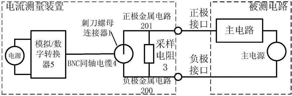
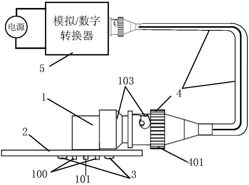
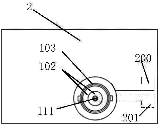
[0021] Figure 1a It is the circuit schematic diagram of the current measuring device of the present invention. Such as Figure 1a As shown, the sampling resistor 3 in the current measuring device of the present invention is respectively connected to the positive interface and the negative interface of the circuit under test through the positive metal circuit 201 and the negative metal circuit 200 on the printed circuit board 2, and the sampling resistor 3 It is connected in series between the positive interface and the negative interface of the circuit under test, and is connected in parallel with the positive and negative poles of the bayonet nut connector 1 through the two metal circuits 201 and 200 . The positive and negative pole voltages of the bayonet nut connector 1 are the voltage on the sampling resistor 3, and the voltage is in a con...


PUM


Abstract

A current measuring device, comprising a current measuring device bayonet nut connector (1), a printed circuit board (2), a sampling resistor (3), an analog / digital converter (5), and connecting the bayonet nut connector with the analog / digital BNC coaxial cable for digitizer (4). The bayonet nut connector (1) includes a positive pole, a negative pole and an insulating material between the positive pole and the negative pole. The printed circuit board (2) includes an insulating material substrate and a metal circuit. The two ends of the sampling resistor (3) are connected in parallel with the two poles of the bayonet nut connector through the metal circuit on the printed circuit board, and connected in series in the circuit under test. The sampling resistor (3) is welded outside the bayonet nut connector, or built into the bayonet nut connector. The analog / digital converter circuit (5) processes the sampled voltage between the two terminals of the bayonet nut connector, and the BNC coaxial cable (4) is connected to the bayonet nut connector (1).

Description

technical field [0001] The invention relates to a current measuring device. Background technique [0002] With the wide application of power electronics technology in various industries, the requirements for current measurement devices and technologies in the control and protection of power electronics equipment are getting higher and higher. In the field of precise control and high-speed control, the current measuring device is required to be not only accurate and fast, but also simple in structure and low in cost. The commonly used current measurement tools are Rogowski coils and current clamps. These two measurement tools are widely used in the measurement of large currents and AC changes. Noise interference, large measurement error, and long measurement delay time are not conducive to precise and fast control, and the cost of the Rogowski coil is high. [0003] Patent CN103123369A provides an induction device for current measurement through a magnetic field collection ...

Claims


Application Information

Patent Timeline
Patent Type & Authority Patents(China)
IPC IPC(8): G01R19/25
Inventor 孟金磊宁圃奇温旭辉孔亮张瑾李二良
Owner 菲仕绿能科技(北京)有限公司
Why Eureka
Try Eureka