
Curved display panel and curved display device

A curved surface display device and curved surface display technology, applied in nonlinear optics, instruments, optics, etc., can solve the problems of electric field changes, curved surface display darkening, etc., and achieve the effect of reducing dark lines and improving display quality

Active Publication Date: 2016-08-17
TCL CHINA STAR OPTOELECTRONICS TECH CO LTD
View PDF4 Cites 0 Cited by
  • Summary
  • Abstract
  • Description
  • Claims
  • Application Information

AI Technical Summary

Problems solved by technology

[0005] In the process of making a curved display, since the upper and lower substrates are based on the center of the panel, there will be a relative shift (shift) to the left and right sides in the horizontal direction. The electric field in the cell will change, causing the position near the ITO Trunk in the curved display to be dark

Method used


Image

  • Curved display panel and curved display device
  • Curved display panel and curved display device
  • Curved display panel and curved display device

Examples


Embodiment Construction

[0026] The word "embodiment" as used in this specification means serving as an example, instance or illustration. Furthermore, the article "a" as used in this specification and the appended claims may generally be construed to mean "one or more" unless specified otherwise or clear from the context in the singular.

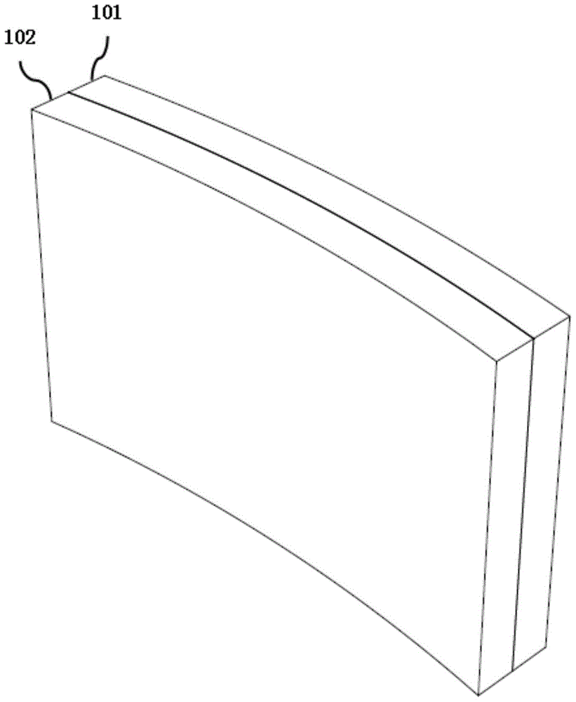
[0027] refer to figure 1 and figure 2 , figure 1 is a schematic diagram of the curved surface display device of the present invention, figure 2 for figure 1 A schematic cross-sectional view of the curved display panel 102 in .

[0028] The curved display device of this embodiment includes a curved backlight module 101 and a curved display panel 102 , and the curved display panel 102 is superposed and combined with the curved backlight module 101 .

[0029] The curved display panel 102 includes a curved color filter substrate 203 , a liquid crystal layer 202 and a curved TFT array substrate 201 .

[0030] Wherein, the curved color filter substrate 203 includ...


PUM


Abstract

Provided are a curved-surface display panel (102) and a curved-surface display apparatus, which can reduce hidden lines in border regions of different sub-regions in pixel electrodes (304). The curved-surface display panel (102) comprises a curved-surface color filter substrate (203), a liquid crystal layer (202), and a curved-surface thin film transistor array substrate (201). The curved-surface color filter substrate (203) comprises a first curved-surface substrate (405), a color resistance array layer (406), a first protection layer (408), and a common electrode (409). The curved-surface thin film transistor array substrate (201) comprises a second curved-surface substrate (401) and a pixel array layer.

Description

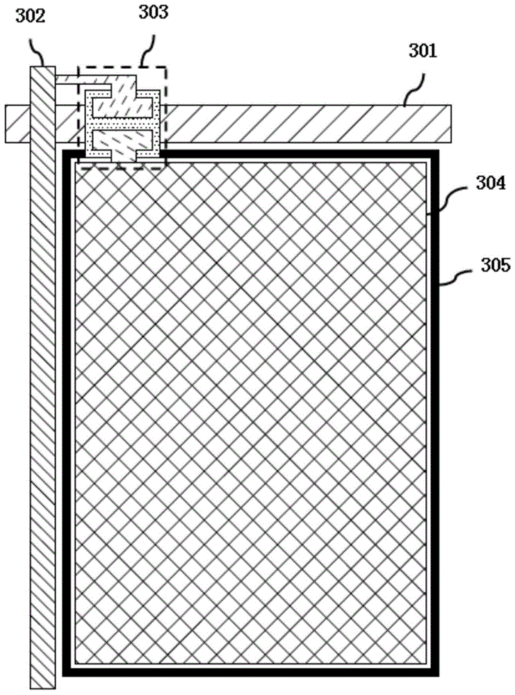
【Technical field】 [0001] The invention relates to the field of display technology, in particular to a curved display panel and a curved display device. 【Background technique】 [0002] In a traditional VA (Vertical Alignment, Vertical Alignment) display, in order to solve the color shift problem of the viewing angle, the sub-pixel (Sub-pixel) is generally divided into several domains (Domain). [0003] The pixel unit in the sub-pixel usually has a fishbone structure, and the boundary area between the partitions is generally called an ITO (Indium Tin Oxide, Indium Tin Oxide) Trunk (trunk). [0004] As the number of partitions increases, the number of ITO Trunks will also increase. [0005] In the process of making a curved display, since the upper and lower substrates are based on the center of the panel, there will be a relative shift (shift) to the left and right sides in the horizontal direction. The electric field in the cell will change, causing the position near the IT...

Claims


Application Information

Patent Timeline
Patent Type & Authority Patents(China)
IPC IPC(8): G02F1/1335G02F1/1368G02F1/1343
CPCG02F1/1343
Inventor 吴川王醉
Owner TCL CHINA STAR OPTOELECTRONICS TECH CO LTD
Learn More