Smart switch, control method thereof, smart control network

A technology of intelligent switch and control method, which is applied in the field of switches, can solve the problems of relay damage, short life of relay electronic switches, large impact voltage, etc., and achieve the effect of prolonging life, low cost and realizing self-adaptation

Inactive Publication Date: 2015-01-21
HAIER GRP CORP +1
View PDF4 Cites 8 Cited by
  • Summary
  • Abstract
  • Description
  • Claims
  • Application Information

AI Technical Summary

Problems solved by technology

[0002] In the field of switch control, the opening and closing of the load is usually controlled by driving the relay action. When the relay is closed or disconnected, a large impulse voltage is often generated, causing damage to the relay, causing damage to the relay or an electronic switch with a relay. shorter lifespan

Method used


Image

  • Smart switch, control method thereof, smart control network
  • Smart switch, control method thereof, smart control network
  • Smart switch, control method thereof, smart control network

Examples


Embodiment 1

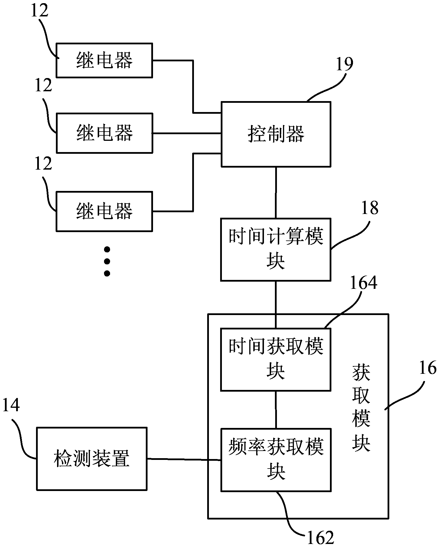
[0026] figure 1 A block diagram of an intelligent switch provided by Embodiment 1 of the present invention. The smart switch is connected with a load, which is specifically used to control the state of the load. In an optional structure, the smart switch may be provided with a local input module, and the local input module may include, for example, a . Buttons used to control the load connected to the smart switch; for example, a remote communication module may also be provided on the smart switch to remotely receive control instructions from other smart switches so that the smart switch controls the load connected to it state.

[0027] Such as figure 1 As shown, the smart switch provided in this embodiment includes: at least one relay 12, a detection device 14, an acquisition module 16, a time calculation module 18 and a controller 19, the acquisition module 16 is connected with the detection device 14 and the time calculation module 18, and the time calculation Module 18 ...

Embodiment 2

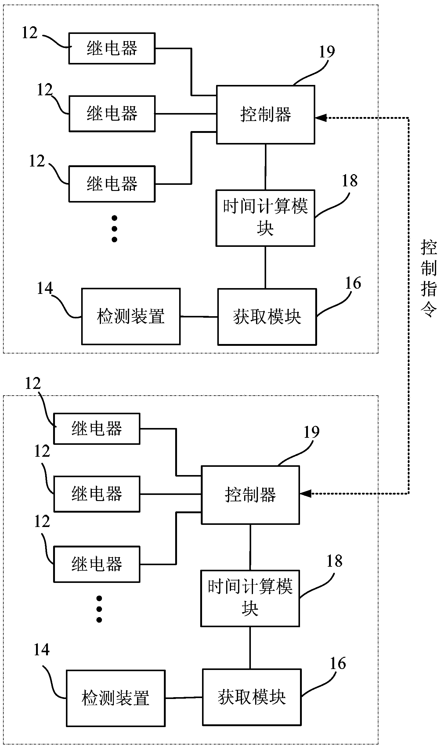
[0051] image 3 It is a block diagram of an intelligent control network provided by Embodiment 2 of the present invention. Such as image 3 As shown, the intelligent control network includes the above-mentioned intelligent switch, and the intelligent switch is connected with a load.

[0052] The intelligent control network of this embodiment can include a plurality of intelligent switches, and each intelligent switch can send control instructions to the controller 19 of other intelligent switches in a remote manner, and each intelligent switch can include a plurality of relays, the multiple The relays are connected to different loads. When the state of a load that needs to be controlled by one of the smart switches changes, the controller 19 can obtain control commands under the trigger of the corresponding local keys, or remotely receive corresponding control commands from other smart switches. And control the corresponding relay 12 to make it act near the zero phase of the...

Embodiment 3

[0056] Figure 4 It is a flow chart of a method for controlling an intelligent switch provided by Embodiment 3 of the present invention. Such as Figure 4 As shown, the method includes the following steps S41, S43, S45, and S47.

[0057] Step S41: Obtain a control instruction of the controlled load;

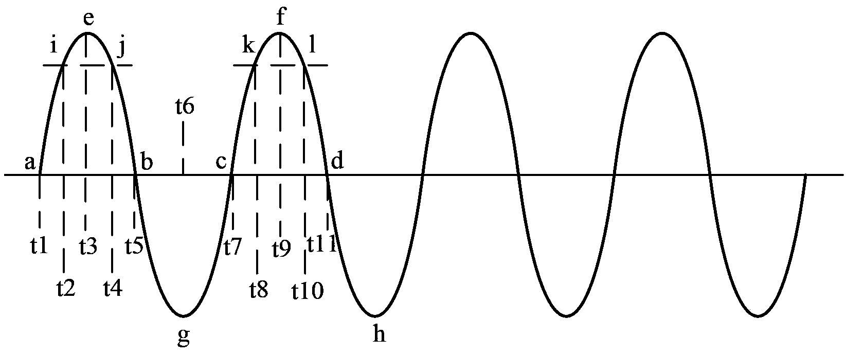
[0058] Step S43: Detecting the instantaneous value of the alternating current passing through the relay connected to the controlled load;

[0059] Step S45: Determine the frequency of the alternating current according to the variation relationship of the instantaneous value with time, and obtain the time point of the zero crossing of the alternating current through the frequency;

[0060] Step S47: According to the time point of the AC zero-crossing point and the relay action delay time, determine the time point for controlling the action of the relay;

[0061] Step S49: Control the action of the relay according to the time point when the control relay is actioned.

[0062] ...


PUM


Abstract

The invention relates to a smart switch, a control method thereof, a smart control network. The control method includes the following steps that: control commands of a controlled load are obtained; according to a relationship that the instantaneous value changes with time, the frequency of alternating current is determined, and a time point of zero crossing of the alternating current is obtained according to the frequency; a time point of the action of the relay is determined according to the time point of zero crossing of the alternating current and action delay time of the relay; and the relay is controlled to act according to the time point of the action of the relay. With the smart switch, the control method thereof and the smart control network of the invention adopted, the relay and the smart switch can be effectively protected, and the service lives of the relay and the smart switch can be prolonged, and the action time of the relay can be flexibly determined according to the action relay time of the relay, and therefore, the control method can be adaptive to different relays.

Description

technical field [0001] The invention relates to the technical field of switches, in particular to an intelligent switch, a control method thereof, and an intelligent control network. Background technique [0002] In the field of switch control, the opening and closing of the load is usually controlled by driving the relay action. When the relay is closed or disconnected, a large impulse voltage is often generated, causing damage to the relay, causing damage to the relay or an electronic switch with a relay. Shorter lifespan. Contents of the invention [0003] A brief overview of the invention is given below in order to provide a basic understanding of some aspects of the invention. It should be understood that this summary is not an exhaustive overview of the invention. It is not intended to identify key or critical parts of the invention nor to delineate the scope of the invention. Its purpose is merely to present some concepts in a simplified form as a prelude to the ...

Claims


Application Information

Patent Timeline
Patent Type & Authority Applications(China)
IPC IPC(8): G09B19/04G01R19/175
CPCG05B19/04
Inventor 徐志方郇延文张洪波
Owner HAIER GRP CORP
Why Eureka
Try Eureka