PCBA positioning tool and positioning method of PCBA compression joint technology

A tool and process technology, applied in the field of PCBA positioning tools and positioning, can solve the problems of low centering efficiency, difficult centering, and inability to extend the pins, so as to improve the centering accuracy, reduce the centering difficulty, and shorten the centering. medium time effect

Inactive Publication Date: 2015-01-21
ZHUZHOU CSR TIMES ELECTRIC CO LTD
View PDF4 Cites 0 Cited by
  • Summary
  • Abstract
  • Description
  • Claims
  • Application Information

AI Technical Summary

Problems solved by technology

As the PCBA becomes more and more complex, some plug-ins begin to use 2.0pitch crimp connectors. The component pins of such connectors cannot protrude from the PCB before crimping.
For the case where the component pins cannot protrude from the PCB before crimping, it is impossible to directly see the correspondence between the component hole on the back of the PCB and the seam of the crimping die. High difficulty and low alignment efficiency

Method used


Image

  • PCBA positioning tool and positioning method of PCBA compression joint technology
  • PCBA positioning tool and positioning method of PCBA compression joint technology
  • PCBA positioning tool and positioning method of PCBA compression joint technology

Examples


Embodiment Construction

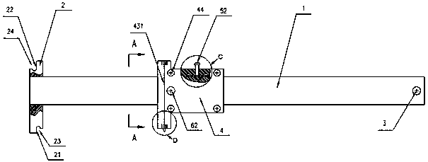
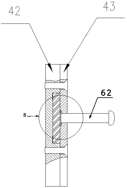
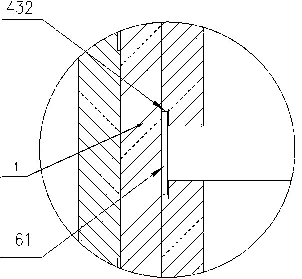
[0038] Such as Figures 1 to 2 As shown, an embodiment of the positioning tool of the present invention includes a main ruler 1, a base block 2 and a vernier 4, wherein the base block 2 is perpendicular to the main ruler 1, and is fixed on the left end of the main ruler 1, and there is a The lower right notch 23 facing right, the left elevation of the lower right notch 23 is the PCB side positioning surface 21, the upper left corner of the base block 2 has a left upper notch 24 facing left, and the right elevation of the left upper notch 24 is crimping The equipment fixture positioning surface 22, the crimping equipment fixture positioning surface 22 and the PCB side positioning surface 21 are located on the same plane, the cursor 4 includes a guide box 42, a front cover 43 and a positioning pin 41, the guide box 42 and the front cover 43 Fixed by fastening screws 44, a hollow through hole is formed between the guide box 42 and the front cover 43, the main scale 1 passes throu...


PUM


Abstract

The invention discloses a PCBA positioning tool and a positioning method of a PCBA compression joint technology. The positioning tool comprises a main ruler, a base block and a vernier, wherein the base block is arranged at the left end of the main ruler and perpendicular to the main ruler, and notches are formed in the lower right corner and the upper left corner of the base block respectively and provided with a compression joint equipment clamp positioning face and a PCB side edge positioning face which are perpendicular to the main ruler and located in the same plane; the vernier comprises a guiding box, a front cover and a positioning needle, a hollow through hole is formed between the guiding box and the front cover, the main ruler penetrates through the through hole, and the vertex of the positioning needle, a centering scale mark of the guiding box and a centering scale mark of the front cover are aligned. The positioning method includes the steps that the distance from a component hole to the PCB side edge is measured through the positioning needle and the PCB side edge positioning face, a seam of a compression joint lower die is centered through the centering scale mark of the guiding box, the side edge of a compression joint equipment clamp is moved to be tightly attached to the compression joint equipment clamp positioning face, a PCB is placed on the compression joint lower die, and the PCB side edge is clamped through the compression joint equipment clamp. Accurate centering of the component hole and the seam of the compression joint lower die is achieved, and the time for PCBA positioning is shortened.

Description

technical field [0001] The invention relates to the technical field of electronic production and manufacturing, in particular to a PCBA positioning tool and a positioning method for a PCBA crimping process. Background technique [0002] In the PCBA crimping process, it is necessary to align the component hole with the seam of the crimping die. The existing centering method is to place the PCB on the crimping die, then insert the pins of the crimping connector into the PCB component holes, and use the part of the pins protruding from the component holes on the back of the PCB to directly visually inspect the component holes and the crimping parts. Check whether the seam of the lower mold is centered. As the PCBA becomes more and more complex, some plug-ins begin to use 2.0pitch crimping connectors. The component pins of this type of connectors cannot protrude from the PCB before crimping. For the case where the component pins cannot protrude from the PCB before crimping, it...

Claims


Application Information

Patent Timeline
IPC IPC(8): H05K3/30B25B11/00
CPCB25B11/00H05K3/30
Inventor 王卫平潘祥虎吴伟辉温占燕桂晟偲俞鹏程
Owner ZHUZHOU CSR TIMES ELECTRIC CO LTD
Why Eureka
Try Eureka