Diaphragm valve

A diaphragm valve, diaphragm technology, applied in the direction of diaphragm valve, diaphragm, valve details, etc., can solve problems affecting life, high stress, etc., and achieve the effect of high sealing quality

Active Publication Date: 2015-01-21
FESTO AG & CO KG
View PDF16 Cites 6 Cited by
  • Summary
  • Abstract
  • Description
  • Claims
  • Application Information

AI Technical Summary

Problems solved by technology

A disadvantage of known diaphragm valves is that the sealing diaphragm is temporarily strongly stretched during switching of the valve parts and is therefore subjected to high stresses, which can adversely affect the service life
During the pivoting of the diaphragm carrier, the diaphragm section of the sealing diaphragm surrounding the diaphragm carrier is subjected to high tensile stresses, which can affect the service life

Method used


Image

  • Diaphragm valve
  • Diaphragm valve
  • Diaphragm valve

Examples


Embodiment Construction

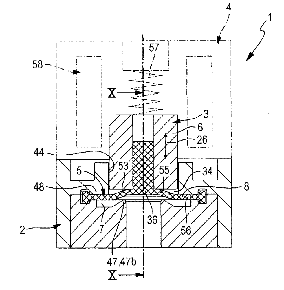
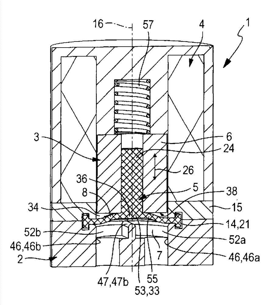
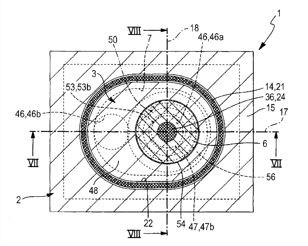
[0038] In all exemplary embodiments, the diaphragm valve, which is designated as a whole by the reference numeral 1 , has a valve housing 2 and a valve part 3 arranged in the valve housing 2 that is movable relative to the valve housing 2 . Furthermore, the diaphragm valve 1 is equipped with an electrically actuatable drive means 4 , preferably arranged in the interior of the valve housing 2 , by means of which the valve part 3 can be switched between two possible switching positions. figure 1 and 2 And 7 and 8 correspondingly show the first switching position, which is the closed position. Figures 4 to 6 And 10 and 11 correspondingly show the second switching position, which is for example the open position.

[0039] The valve part 3 is preferably designed as a composite element consisting of a membrane body 5 and at least one membrane carrier 6 carrying the membrane body 5 . These components are fixed to one another in a manner that will be explained further. Whereas the...


PUM


Abstract

The invention relates to a diaphragm valve (1) having a valve housing (2) and a valve member (3) movable relative to said housing. The valve member (3) comprises a diaphragm carrier (6) that can be driven to execute a switchover motion (26) having a sealing diaphragm (8) mounted thereon, which delimits a valve chamber (7) in which a valve seat (47) is found. The sealing diaphragm (8) has a sealing section (53) opposite said valve seat (47) belonging at least partially to a loose diaphragm section (55) of the sealing diaphragm (8), which can lift from the diaphragm carrier (6) to reduce the stress on the sealing diaphragm (8) when said diaphragm carrier is removed from the valve seat (47) during switching.

Description

technical field [0001] The invention relates to a diaphragm valve with a valve housing and at least one valve part movable therewith, wherein the valve part has a diaphragm carrier which is movable relative to the valve housing when a switching movement is carried out and which is connected to the valve housing A flexible sealing membrane delimiting the valve chamber together with the body, wherein the sealing membrane is fastened in a sealed manner on the valve housing at its outer edge region and has a spaced distance from this and is fixed on the diaphragm carrier and participates in it. Stationary diaphragm section for converting movement, wherein a valve seat facing the sealing diaphragm is arranged in the valve chamber, the sealing section of the sealing diaphragm being at least partially supported by the base surface of the diaphragm carrier facing the valve chamber in a sealable manner Pressed against the valve seat to isolate at least two fluid passages leading into t...

Claims


Application Information

Patent Timeline
Patent Type & Authority Applications(China)
IPC IPC(8): F16K7/12F16K31/06
CPCF16K31/0672F16K7/126F16K31/0641F16K31/10F16K7/14F16K7/12F16K31/02
Inventor A.比勒
Owner FESTO AG & CO KG
Why Eureka
Try Eureka