Multi-functional sickbed

A multi-functional, hospital bed technology, applied in the field of multi-functional hospital beds, can solve the problems of self or fetal injury, inconvenient placement of shoes, easy fall from the bed, etc., to achieve the convenience of wearing shoes, easy cultivation, and increase the rotation angle Effect

Inactive Publication Date: 2015-01-28
王润华
View PDF7 Cites 6 Cited by
  • Summary
  • Abstract
  • Description
  • Claims
  • Application Information

AI Technical Summary

Problems solved by technology

[0002] In real life, during the hospital stay, the patient is unable to move due to his own reasons. When he needs to get out of bed, his shoes are often a certain distance away from the bed. Using feet to reach for shoes or bending over to reach for shoes is a great safety hazard for patients themselves, who can easily fall off the bed and cause damage to themselves or the fetus in the womb
[0003] Such as the notification number CN201366036 Chinese invention patent, a multifunctional bed, which is composed of a bed board and a bed frame. One side of the bed board is provided with a rotating trash can and a movable table. The patient can use the movable head, telescopic rod and bearings to adjust the inclination and height of the desktop; and it can be flipped under the bed board as a shoe rack, so that the table not only does not affect the patient's rest, but also does not take up space and can be used reasonably. However, the bed with this structure requires the patient to adjust the shoe rack, which requires manual It is very inconvenient to get the shoes, it is not convenient to put the shoes, and the structure of the bed is single, and now patients pay more and more attention to the effect of physical therapy, which cannot meet the needs of patients

Method used


Image

  • Multi-functional sickbed
  • Multi-functional sickbed
  • Multi-functional sickbed

Examples


Embodiment Construction

[0032] A preferred embodiment of a multifunctional hospital bed of the present invention will be described in detail below in conjunction with the accompanying drawings.

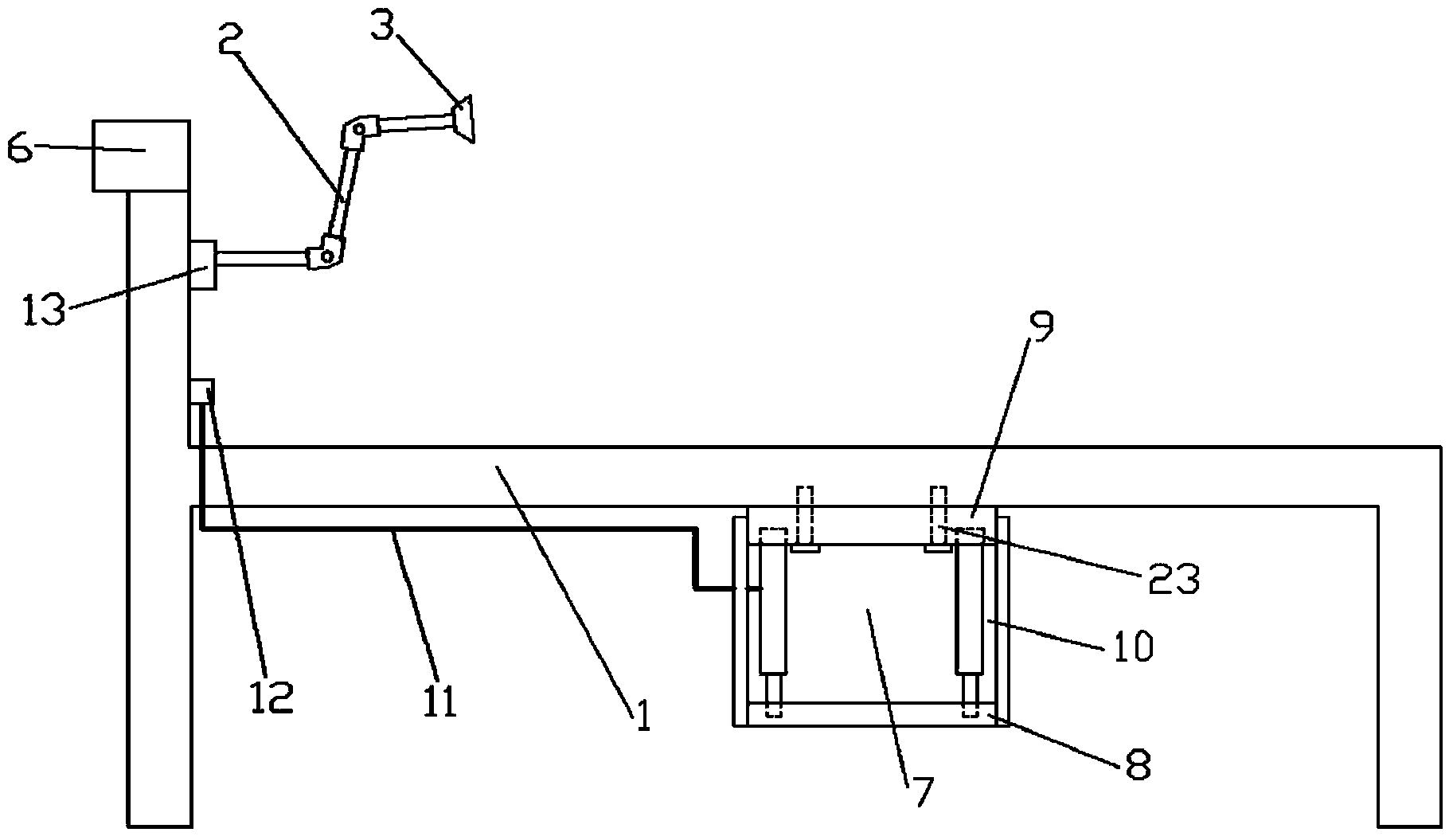
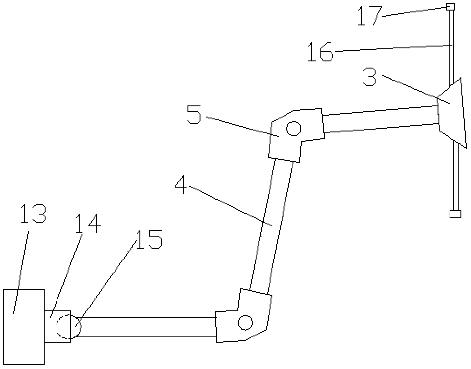
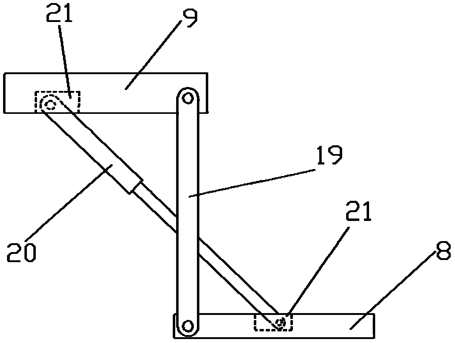
[0033] figure 1 and figure 2 A specific embodiment of a multifunctional hospital bed of the present invention is shown: a multifunctional hospital bed, comprising a hospital bed body, electromagnetic physiotherapy devices are respectively provided on both sides of the head of the hospital bed 1, and the device includes a first linkage mechanism 2 and Electromagnetic head 3, the two ends of first link mechanism 2 are connected with bedside and electromagnetic head 3 respectively, and first link mechanism 2 is connected by universal joint 5 successively by 3 connecting rods 4 head and tail, and bedside place is provided with A storage box 6 for fixing the electromagnetic head 3, a side of the bed bottom of the hospital bed 1 is provided with a shoe rack 7 that can be accommodated, and the shoe rack 7 include...


PUM


Abstract

The invention discloses a multi-functional sickbed and belongs to the field of nursing devices. Both sides of the bedhead of the sickbed are provided with an electromagnetic therapy device respectively, each electromagnetic therapy device comprises a first linkage mechanism and an electromagnetic head, both ends of the first linkage mechanism are connected with the bedhead and the electromagnetic head, the first linkage mechanism comprises three connecting rods connected through cardan joints successively from head to tail, a storage box for fixing the electromagnetic head is arranged at bedhead, one side of the bottom of the sickbed is provided with a storable shoe rack, the shoe rack comprises a lower plate, an upper plate and a second linkage mechanism arranged between the lower plate and the upper plate, the second linkage mechanism is arranged on two corresponding sides of the lower plate and the upper plate respectively, and the bedhead of the sickbed is provided a switch connected with the second linkage mechanism through a control cable and the shoe rack can be controlled through the switch. Therefore, in case that a patient needs to get out of the sickbed, the patient doesn't need to stoop down to grab shoes, and thus great convenience is achieved and electromagnetic physiotherapy can be carried out on patients through the electromagnetic head.

Description

technical field [0001] The invention relates to the field of nursing devices, in particular to a multifunctional hospital bed. Background technique [0002] In real life, during the hospital stay, the patient is unable to move due to his own reasons. When he needs to get out of bed, his shoes are often a certain distance away from the bed. Reaching for shoes with feet or bending over to reach for shoes is a great safety hazard for patients themselves, who can easily fall off the bed and cause damage to themselves or the fetus in the abdomen. [0003] Such as the notification number CN201366036 Chinese invention patent, a multifunctional bed, which is composed of a bed board and a bed frame. One side of the bed board is provided with a rotating trash can and a movable table. The patient can use the movable head, telescopic rod and bearings to adjust the inclination and height of the desktop; and it can be flipped under the bed board as a shoe rack, so that the table not only...

Claims


Application Information

Patent Timeline
Patent Type & Authority Applications(China)
IPC IPC(8): A61G7/00A61G7/05A61N2/00A61N5/06
Inventor 徐鸿
Owner 王润华
Why Eureka
Try Eureka