Automatic electromagnetic impurity removing machine for cigarette
An automatic and electromagnetic technology, applied in the fields of magnetic separation, solid separation, chemical instruments and methods, etc., can solve the problems of many iron impurities, easy damage of key processing parts of equipment, fluctuation of quality of process products, etc., and achieves a high degree of automation. , convenient for parameterized control, the effect of improving the effect of impurity removal
- Summary
- Abstract
- Description
- Claims
- Application Information
AI Technical Summary
Problems solved by technology
Method used
Image

Examples
Embodiment Construction
[0046] The implementation of the present invention will be illustrated by specific specific examples below, and those skilled in the art can easily understand other advantages and effects of the present invention from the contents disclosed in this specification.
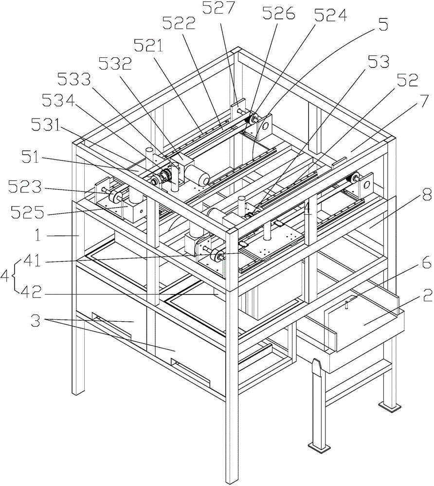
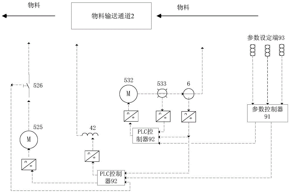
[0047] see Figure 1 to Figure 2 . It should be noted that the structures, proportions, sizes, etc. shown in the drawings attached to this specification are only used to match the content disclosed in the specification, for those who are familiar with this technology to understand and read, and are not used to limit the implementation of the present invention. Limiting conditions, so there is no technical substantive meaning, any modification of structure, change of proportional relationship or adjustment of size, without affecting the effect and purpose of the present invention, should still fall within the scope of the present invention. The disclosed technical content must be within the scope covered. At the sa...
PUM
 Abstract
Description
Claims
Application Information