Double-screw extruder

A twin-screw extruder and twin-screw technology, applied in the field of extrusion molding, can solve problems such as feeding gaps, and achieve the effect of avoiding loss and reducing the rate of defective products

Active Publication Date: 2015-01-28
重庆市南川区利华塑料制品有限责任公司
View PDF5 Cites 10 Cited by
  • Summary
  • Abstract
  • Description
  • Claims
  • Application Information

AI Technical Summary

Problems solved by technology

[0005] The invention provides a twin-screw extruder to solve the problem that there is a gap when feeding the existing twin-screw extruder

Method used


Image

  • Double-screw extruder
  • Double-screw extruder
  • Double-screw extruder

Examples


Embodiment 1

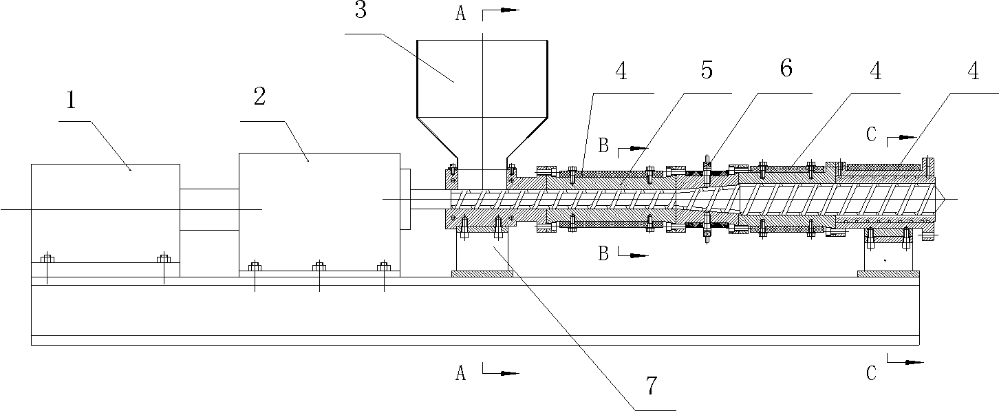
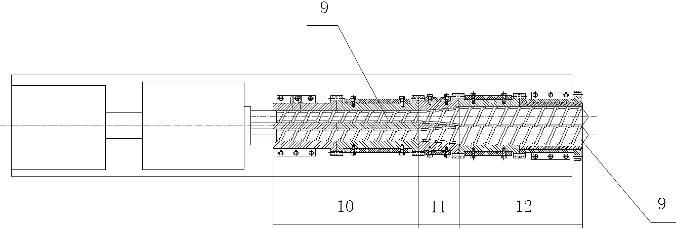
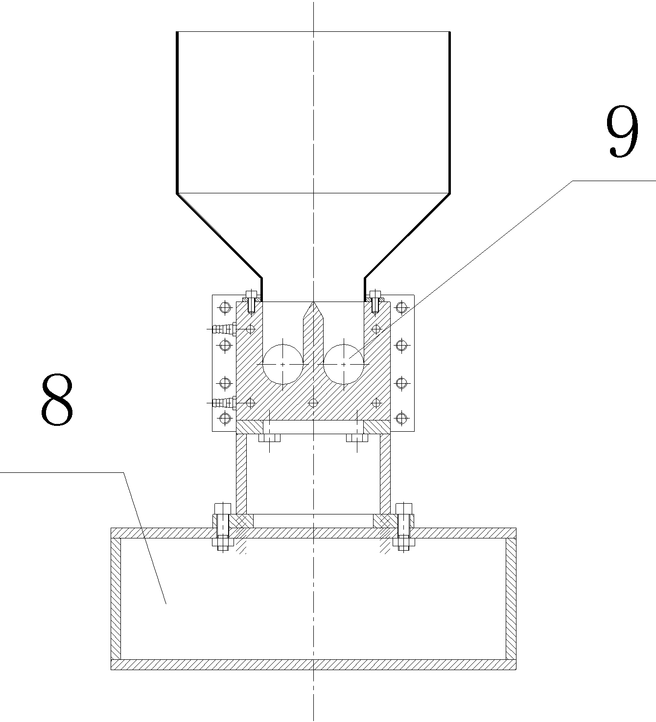
[0023] Such as figure 1 with figure 2 As shown, a twin-screw extruder in this embodiment includes a barrel 5 and a parallel twin-screw 9, and a section inside the barrel 5 is divided into two independent through passages through an interlayer. Both screws 9 are located in the barrel 5, including an independent section 10, a filling section 11 and an engaging section 12 arranged in sequence along the conveying direction of the screws 9 (from left to right). Such as image 3 with Figure 4 As shown, the two screws 9 in the independent section 10 are in a non-engaging state, and the two screws 9 are respectively located in two independent passages through the barrel 5, and an electric heater 4 is provided on the entire section of the barrel. The two rods in the filling section 11 are also in a non-engaging state. The two screw rods 9 are respectively located in the two independent passages of the barrel 5. The injection section is provided with a filler 6, and the outlet of t...

Embodiment 2

[0038] The difference from Example 1 is that the screw 9 in Example 1 is integral; and the screw 9 in Example 2 is combined: the first screw 9 in the independent section 10 is located in the filling section The second screw 9 in 11 is composed of the third screw 9 in the engaging section 12 .

[0039] The advantage of such setting is: when different screw rods 9 can be replaced according to the mixing situation of materials, when the screw rod 9 of the corresponding section is damaged, only the damaged section screw rod 9 needs to be replaced instead of the screw rods 9 of other sections.

Embodiment 3

[0041] The difference from embodiment 1 is that the screw rod 9 in embodiment 2 is a three-stage type, while the screw rod 9 in embodiment 3 is a two-stage type, that is, the first screw rod located in the independent segment 10 and the filling segment 11 A screw 9 and a second screw 9 located in the engaging section 12 are composed.

[0042] Because we found that the independent section 10 and the filling section 11 have many similar features (such as they do not need to be engaged, and they are all located in the two independent passages of the barrel 5), when it is necessary to replace the different screw 9 , the requirements for the independent section 10 and the filling section 11 are also very similar, and can be replaced as a screw 9.


PUM


Abstract

The invention discloses a double-screw extruder which comprises an extruder barrel, two screw units, an independent section and a filling section, wherein two screw units are positioned in the extruder barrel; a screw unit section in one screw unit is meshed with that in the other screw unit to form a meshed section; a discharging hole is formed in the tail end of the meshed section; two independently communicated flow channels are formed in the extruder barrel; the independent section, the filling section and the meshed section are arranged in sequence along the conveying directions of the screw units; both screw units of each of the independent section and the filling section are in non-meshed states and are positioned in the flow channels respectively; heaters are arranged on the whole section of the extruder barrel; a filler is arranged on the filling section. According to the double-screw extruder, the independent section and the filling section are equivalently two independent single screws; molten materials in the screw grooves of the screws have relatively good sealing effects, so that the loss of added gas and supercritical fluid is avoided; the meshed section has a relatively good dispersive mixing effect on the materials, so that the polymer melt foaming is facilitated.

Description

technical field [0001] The invention belongs to the technical field of extrusion molding. Background technique [0002] The screw refers to a cylinder with a helical groove cut on the outer surface or a cone with a helical groove on the conical surface. Existing extruders often use a screw structure, so that the material gradually changes into a linear motion with the rotation of the screw, and moves toward the machine head, and cooperates with the machine body to compress and generate heat, soften and stir, and mix the materials. [0003] The common screw extruder is a single-screw extruder, and the conveying section and the mixing section are two intermeshing twin-screw extruders. The single-screw extruder relies on the friction generated between the material and the barrel to make the material forward in a way that fills the screw groove. The twin-screw extruder is mainly in a "∞"-shaped barrel. The material in the twin-screw extruder is conveyed forward in a way that t...

Claims


Application Information

Patent Timeline
Patent Type & Authority Applications(China)
IPC IPC(8): B29C47/40B29C47/60
CPCB29C48/0012B29C48/402B29C48/52
Inventor 徐舒
Owner 重庆市南川区利华塑料制品有限责任公司
Why Eureka
Try Eureka