
Method for diagnosing air leakage of vacuum air suction system for providing vacuum degree of brake system

A brake system and vacuum pumping technology, applied in the direction of brake safety system, etc., can solve problems such as false alarms and missed alarms

Active Publication Date: 2015-01-28
UNITED AUTOMOTIVE ELECTRONICS SYST
View PDF7 Cites 22 Cited by
  • Summary
  • Abstract
  • Description
  • Claims
  • Application Information

AI Technical Summary

Problems solved by technology

If the threshold calibration is inaccurate, it will lead to false positives or missed negatives

Method used


Image

  • Method for diagnosing air leakage of vacuum air suction system for providing vacuum degree of brake system
  • Method for diagnosing air leakage of vacuum air suction system for providing vacuum degree of brake system
  • Method for diagnosing air leakage of vacuum air suction system for providing vacuum degree of brake system

Examples


Embodiment Construction

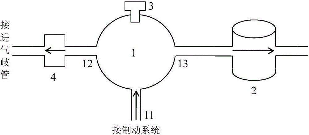
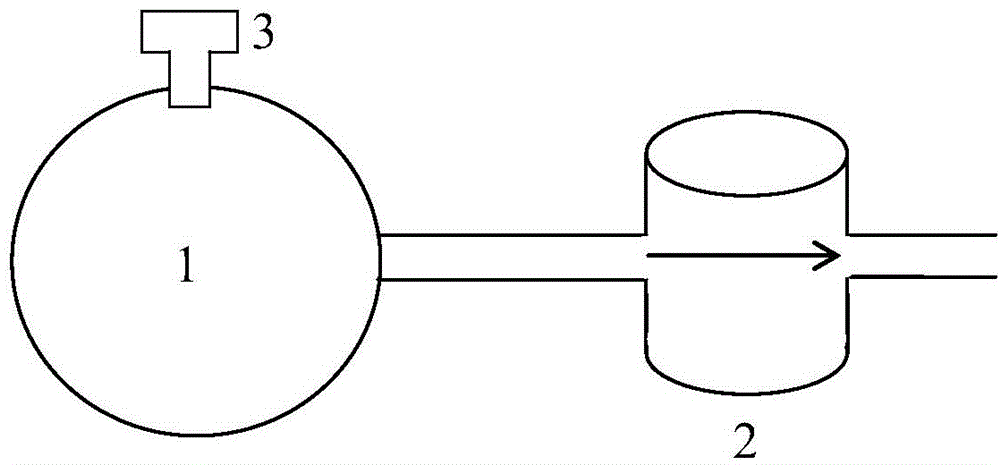
[0038] see image 3 ,this is figure 1 The simplified structure of the vacuum pumping system shown when the diagnostic conditions are met is composed of a vacuum tank 1 , a vacuum pump 2 and a pressure sensor 3 . The vacuum pump 2 only allows the gas in the vacuum tank 1 to be drawn out through the vacuum pump 2, and does not allow the gas to flow in reverse. Compare figure 1 and image 3 it can be discovered, image 3 The air inlet 11 and the first suction port 12 of the vacuum tank 1 are omitted. In fact, figure 1 The vacuum pumping system shown is simplified to image 3 .

[0039] exist image 3 In the shown vacuum pumping system, the vacuum pump 2 is turned on to draw gas from the vacuum tank 1 . At this time, only the leakage gas (including the gas entering the vacuum tank 1 through various gaps, the gas penetrating into the vacuum tank 1 from the container wall, etc.) enters the vacuum tank 1, and only the gas extracted by the vacuum pump 2 leaves the vacuum tank...


PUM


Abstract

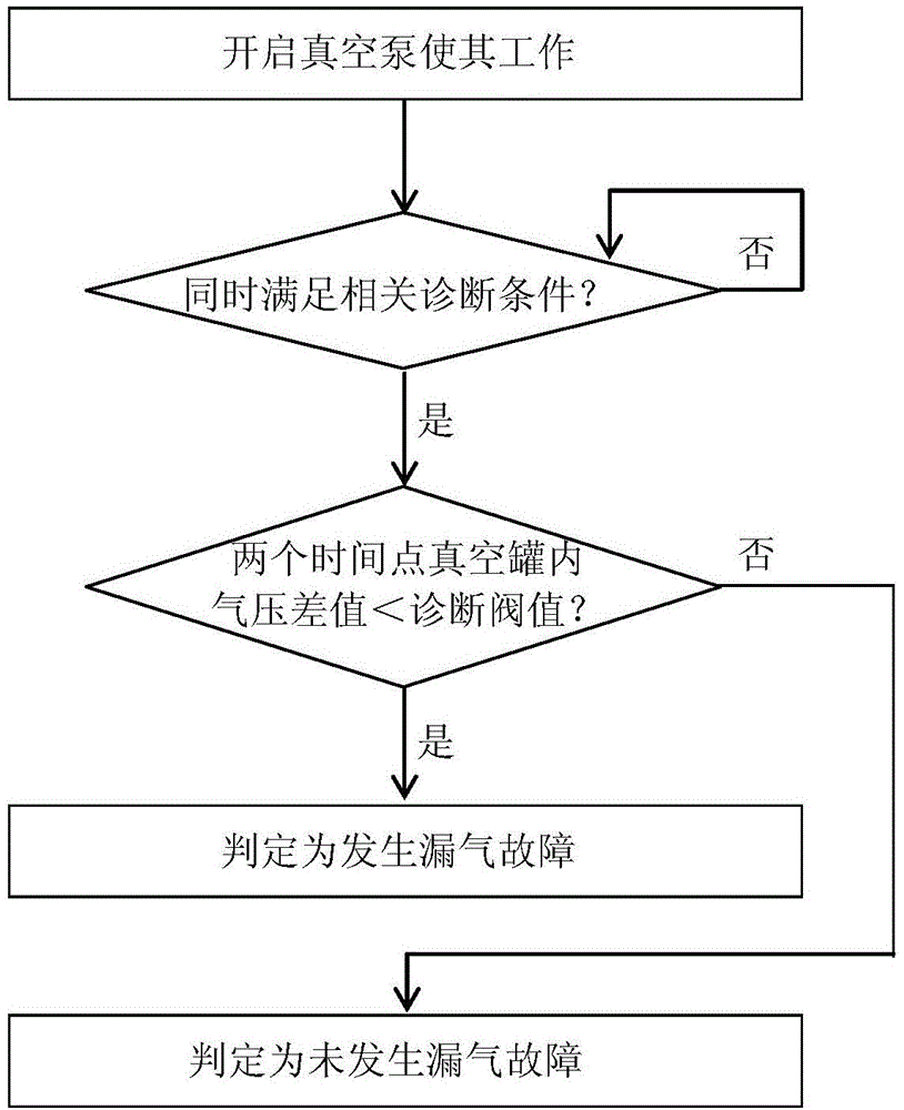
The invention discloses a method for diagnosing air leakage of a vacuum air suction system for providing vacuum degree of a brake system. The method comprises the following steps of 1, opening a vacuum pump to suck air out of a vacuum tank; 2, simultaneously meeting the following three diagnosis conditions, namely that (1) the air in the vacuum tank is only exhausted through the vacuum pump; (2) a brake pedal is not treaded; (3) the working state of a pressure sensor for detecting the air pressure in the vacuum tank is normal; 3, respectively measuring the air pressure in the vacuum tank by the pressure sensor at a time point t1 and a time point 2 within the time range when the three diagnosis conditions are simultaneously met, and calculating the difference value of the air pressure at a time point t1 and the air pressure at a time point 2; according to a formula shown in the attached figure, calculating a diagnosis threshold value from the time point 1 to the time point 2; when the difference value of air pressure is smaller than the diagnosis threshold value, judging that the air leakage fault occurs; when the difference value of air pressure is not smaller than the diagnosis threshold value, judging that the air leakage fault does not occur. The method has the advantage that the more accurate diagnosis results can be obtained.

Description

technical field [0001] The present application relates to a method for diagnosing air leakage of a vacuum pumping system used to provide the vacuum degree of a brake system. Background technique [0002] Vehicles normally use the vacuum in the intake manifold behind the throttle for braking. In order to obtain a more reliable and easy braking effect, some vehicles also have a vacuum pumping system that provides the vacuum of the braking system. [0003] see figure 1 , the vacuum pumping system that provides the vacuum of the brake system mainly includes: [0004] ——The vacuum tank 1 has an air inlet 11 , a first air suction port 12 , and a second air suction port 13 . The air inlet 11 is connected to the braking system of the vehicle. When the brake pedal of the vehicle is not depressed, the air inlet 11 is in a sealed state. When the brake pedal of the vehicle is depressed, gas enters the vacuum tank 1 from the intake port 11 . The first air intake port 12 is connecte...

Claims


Application Information

Patent Timeline
IPC IPC(8): B60T17/22
CPCB60T17/22
Inventor 刘浩龙杨东来
Owner UNITED AUTOMOTIVE ELECTRONICS SYST
Learn More