Double cylinder synchronous and independent control method, system and crane

A separate control and separate technology, applied in the field of hydraulic control, can solve problems such as the failure of the large cylinder chamber to be locked, the failure of the separate control strategy of the system, and the low efficiency of the balance weight coupling, so as to achieve the effect of improving efficiency

Inactive Publication Date: 2015-01-28
XUZHOU HEAVY MASCH CO LTD
View PDF5 Cites 4 Cited by
  • Summary
  • Abstract
  • Description
  • Claims
  • Application Information

AI Technical Summary

Problems solved by technology

[0006] However, when the existing double-cylinder synchronous hydraulic system is controlled separately, when one side of the cylinder performs a single drop action, the small cavity of the other side of the cylinder has pressure suppression, and the control oil on the side of the small cavity of the balance valve of the cylinder is high pressure, causing the large cavity of the cylinder to lock. If there is leakage in the reversing valve, the separate control strategy of this system will fail, resulting in low efficiency of the balance weight connection

Method used


Image

  • Double cylinder synchronous and independent control method, system and crane
  • Double cylinder synchronous and independent control method, system and crane
  • Double cylinder synchronous and independent control method, system and crane

Examples


no. 1 example

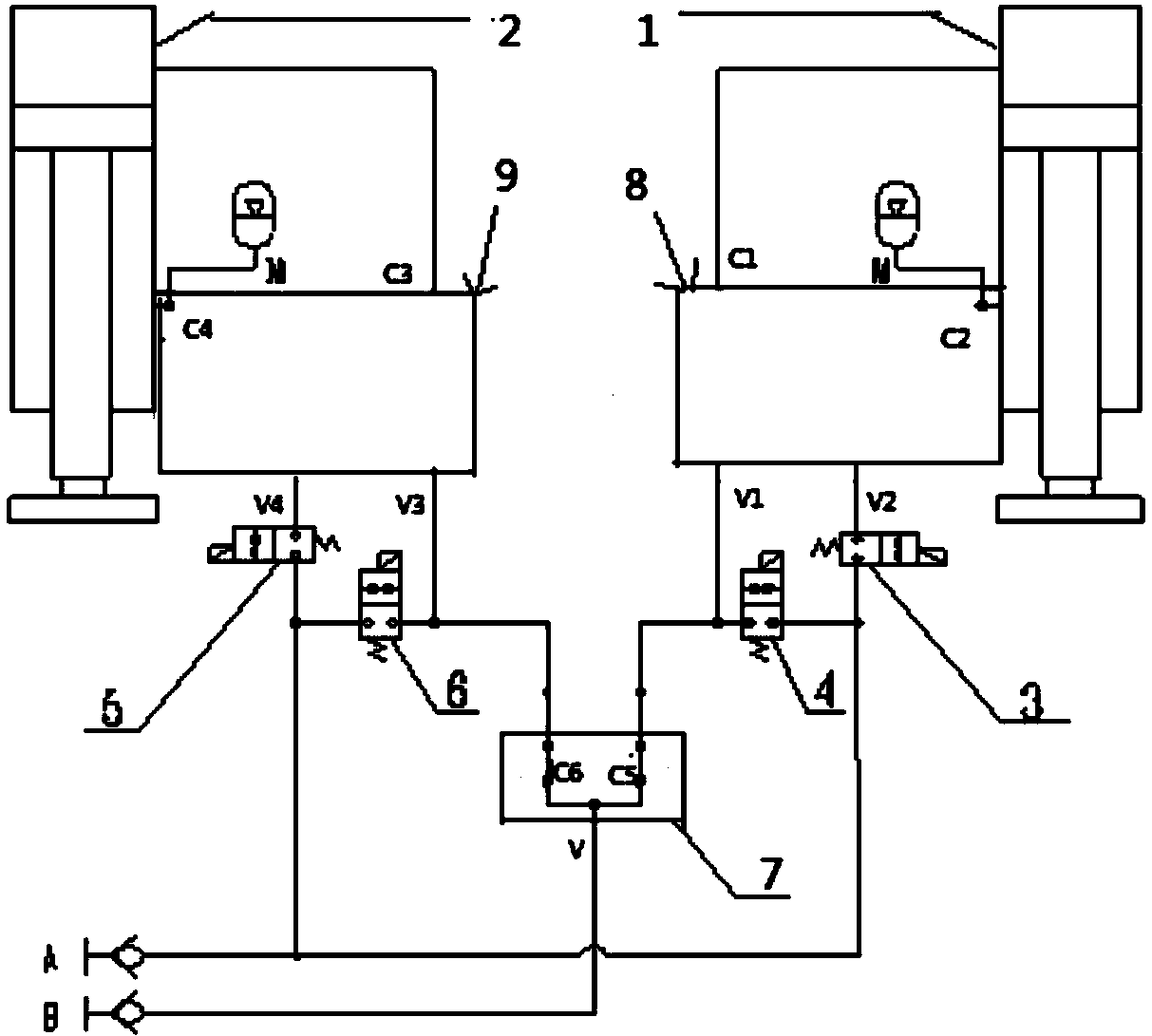
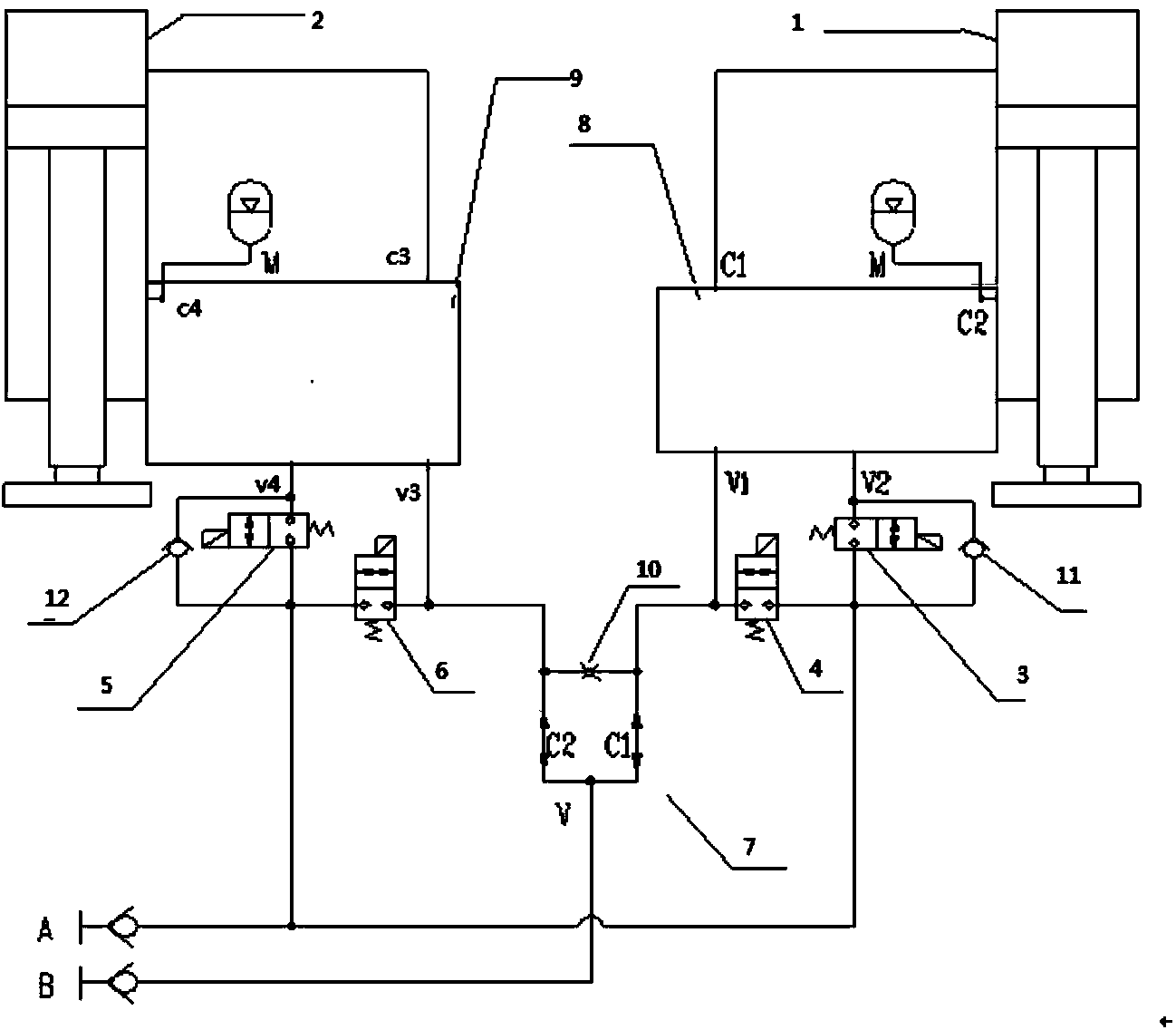
[0104] When the first oil circuit A is connected to the low-pressure oil return and the second oil circuit B is connected to the high-pressure oil inlet, the first on-off valve 3 and the third on-off valve 5 are energized, and the second on-off valve 4 and the fourth on-off valve 6 are not energized. , the hydraulic oil enters the rodless cavity of the first oil cylinder 1 and the second oil cylinder 2 respectively through the diverter and converging valve 7, and the hydraulic oil in the rod cavity returns to the oil through the first switch valve 3 and the third switch valve 5 respectively, realizing the second The first oil cylinder 1 and the second oil cylinder 2 are lifted simultaneously.

no. 2 example

[0106] When the first oil circuit A is connected to the high-pressure oil inlet and the second oil circuit B is connected to the low-pressure oil return, the first on-off valve 3 and the third on-off valve 5 are energized, and when the second on-off valve 4 and the fourth on-off valve 6 are not energized , the hydraulic oil enters the rod cavity of the first oil cylinder 1 and the second oil cylinder 2 through the first switch valve 3 and the third switch valve 5 respectively, and the hydraulic oil in the rodless cavity returns to the oil through the diverter and collector valve 7 to realize the first oil cylinder 1 and the second oil cylinder 2 fall simultaneously.

no. 3 example

[0108] When the first oil circuit A is connected to the low-pressure oil return, and the second oil circuit B is connected to the high-pressure oil inlet, the first on-off valve 3 and the fourth on-off valve 6 are energized, and the second on-off valve 4 and the third on-off valve 5 are not energized. A part of the hydraulic oil returns directly to the oil tank through the fourth switch valve 6, the second oil cylinder 2 does not operate, a part of the hydraulic oil enters the rodless chamber of the first oil cylinder 1, and the hydraulic oil in the rod chamber of the first oil cylinder 1 passes through the first switch valve 3 times Oil, to realize the first oil cylinder 1 lifting alone.


PUM


Abstract

The invention discloses a double cylinder synchronous and independent control method, a system and a crane. The system is provided with four switch valves, wherein the first switch valve and the third switch valve are arranged on a first oil circuit and connected with a fourth oil port and an eighth oil port respectively; the second switch valve and the fourth switch valve are arranged between the first oil circuit and a second oil circuit; one end of the second switch valve is connected with an intersection between a first oil port and a first shunt port; the other end of the second switch valve is connected with one end, far away from the fourth oil port, of the first switch valve; one end of the fourth switch valve is connected with an intersection between a fifth oil port and a second shunt port; and the other end of the fourth switch valve is connected with one end, far away from the eighth oil port, of the third switch valve. Synchronous motion and independent motion of double cylinders are achieved by opening and closing of each switch valve, and the efficiency of the double cylinders to lift a counterweight for hooking is improved.

Description

technical field [0001] The invention relates to the technical field of hydraulic control, in particular to a double-cylinder synchronous and independent control method, system and crane. Background technique [0002] With the continuous increase of the lifting tonnage of large-tonnage cranes, the weight and number of counterweights set are also increasing, and dual hydraulic cylinders are often used for lifting counterweights. The existing balance weight oil cylinder mostly uses the cylinder to carry the weight of the balance weight and transmit the gravity. The installation of the balance weights on both sides is generally symmetrically arranged. In fact, there is an error in the weight of a single small balance weight on both sides, or the center of gravity of the balance weight bracket In the process of connecting the balance weight, the balance weight will produce an eccentric load force on the balance weight cylinder, resulting in different loads on the two balance weig...

Claims


Application Information

Patent Timeline
Patent Type & Authority Applications(China)
IPC IPC(8): B66C13/20F15B11/16F15B11/22
CPCB66C13/20F15B11/22F15B13/06
Inventor 王守伟任印美冀建飞赵磊周飞鹏
Owner XUZHOU HEAVY MASCH CO LTD
Why Eureka
Try Eureka