
A nest connector and its manufacturing method

A technology of connectors and cells, which is applied in the field of connectors connecting honeycomb restraint systems or geocell cells, can solve the problems of no anchoring effect, difficult cutting or drilling, and heavy workload, etc., and achieves good connection effect , wide application range and simple structure

Inactive Publication Date: 2016-03-30
WUHAN GAN SHI DAI ENVIRONMENT RESOURCE TECHCO
View PDF5 Cites 0 Cited by
  • Summary
  • Abstract
  • Description
  • Claims
  • Application Information

AI Technical Summary

Problems solved by technology

[0003] There are mainly two types of connectors in existing honeycomb restraint systems or geocells. One connector is fixed on the ribs of the geocell by injection molding. Injection molding, simple structure, good connection effect, but the strength is often not enough. When the ribs are disturbed by external force, because the connectors are fixedly connected with the ribs, the connectors are easy to collapse when the external force is large, and the damaged connectors are not easy to peel off the ribs. , so it is inconvenient for the inspection and maintenance of the geocell; another kind of connector is inserted in the rib, which can be separated from the rib, and it is more flexible to use, but this kind of connector needs to be cut or drilled on the rib during installation. , the strength of the ribs is reduced after slit or drilled, and it is often not easy to slit or drill for stiffer tendons
[0004] Since the above two connectors have no anchoring effect, it is often necessary to set up additional anchors to fix the honeycomb restraint system or geocell when laying the honeycomb restraint system or geocell. The workload is large and the laying of the honeycomb restraint system or geocell high cost

Method used


Image

  • A nest connector and its manufacturing method
  • A nest connector and its manufacturing method
  • A nest connector and its manufacturing method

Examples


Embodiment Construction

[0026] The present invention will be described in detail below in conjunction with the accompanying drawings and embodiments.

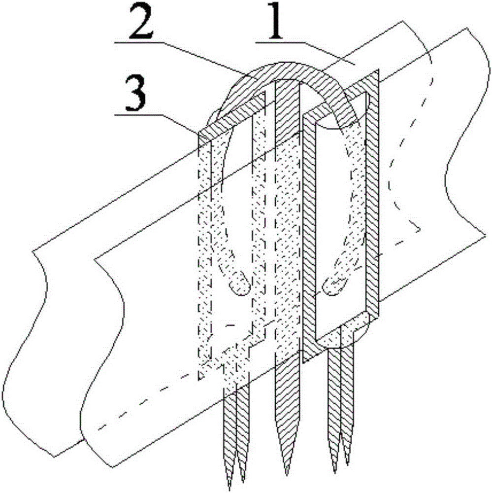
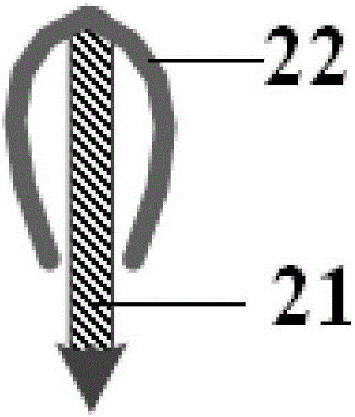
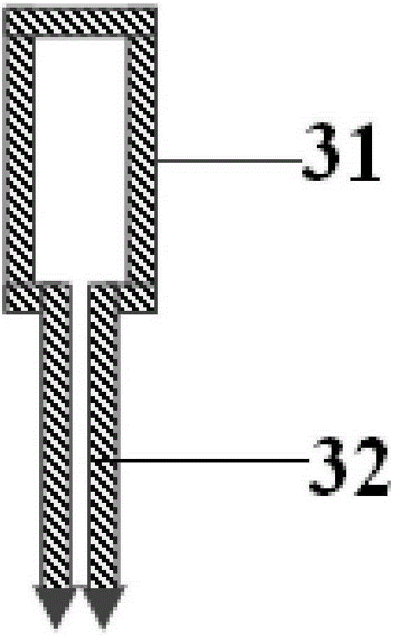
[0027] The cell connector provided by the invention has a structure such as figure 1 As shown, it includes two collars 3 parallel to each other and an insert 2 connecting the two collars; the structure of the insert is as follows figure 2 As shown, it includes a main rod 21 and an arc-shaped shrinking buckle 22 with an opening. The main rod passes through the opening and is embedded in the arc-shaped shrinking buckle, and its upper end is fixedly connected with the arc-shaped shrinking buckle. The rod is symmetrical, and two pin arms are formed on both sides of the main rod, and the bottom ends of the two pin arms shrink toward the opening to form a constriction; the structure of the collar is as follows image 3 As shown, the upper half of the collar is a square frame 31, the lower half is an anchor rod 32, the upper end of the anchor rod is fixedl...


PUM


Abstract

The invention provides a honeycomb chamber connecting piece. The honeycomb chamber connecting piece comprises two mutually parallel sleeve rings and an inserting piece which connects the two sleeve rings, the upper half portions of the sleeve rings are square frames, the lower half portions of the sleeve rings are anchor rods, upper ends of the anchor rods are fixedly connected with bottom edges of the square frames, the anchor rods and the square frames are located on the same plane, the inserting piece comprises a main rod and an arc-shaped necking buckle with an opening, the main rod penetrates the opening to be embedded into the arc-shaped necking buckle, the upper end of the main rod is fixedly connected with the arc-shaped necking buckle, the arc-shaped necking buckle is symmetrical along the main rod, two pin arms are formed on two sides of the main rod, bottom ends of the two pin arms are contracted inwards towards the opening to form a necking opening, the two sleeve rings are located on two sides of the main rod respectively, the plane where the sleeve rings are located is vertical to the plane where the arc-shaped necking buckle is located, and the two pin arms of the arc-shaped necking buckle are buckled in the square frames of the sleeve rings. The invention correspondingly provides a manufacturing method of the connecting piece. The connecting piece is simple in structure, convenient to manufacture, good in connecting effect, capable of achieving anchoring function on a connected honeycomb chamber and wide in application range.

Description

technical field [0001] The invention relates to a connecting piece, in particular to a connecting piece used for connecting honeycomb restraint systems or geocell cells. Background technique [0002] Honeycomb restraint system or geocell is a commonly used geotechnical material. During the construction process, due to the limited length of the sheet, it is necessary to connect multiple honeycomb restraint systems or geocells to meet the laying requirements. [0003] There are mainly two types of connectors in existing honeycomb restraint systems or geocells. One connector is fixed on the ribs of the geocell by injection molding. Injection molding, simple structure, good connection effect, but the strength is often not enough. When the ribs are disturbed by external force, because the connectors are fixedly connected with the ribs, the connectors are easy to collapse when the external force is large, and the damaged connectors are not easy to peel off the ribs. , so it is in...

Claims


Application Information

Patent Timeline
Patent Type & Authority Patents(China)
IPC IPC(8): E02D3/00
CPCE02D3/00E02D3/005E02D5/74E02D2300/0006E02D2300/0026E02D2300/0084E02D2600/30
Inventor 孙晨旭杨金艳
Owner WUHAN GAN SHI DAI ENVIRONMENT RESOURCE TECHCO
Learn More