
Rapid asphalt paving and maintaining device based on municipal road engineering

A technology for municipal roads and maintenance devices, which is applied to roads, roads, and road repairs, etc., can solve problems such as slowing down of running speed, slow paving speed of asphalt paver, and different thickness of paving materials.

Inactive Publication Date: 2017-11-10
卢晓惠
View PDF1 Cites 1 Cited by
  • Summary
  • Abstract
  • Description
  • Claims
  • Application Information

AI Technical Summary

Problems solved by technology

[0005] Aiming at the deficiencies in the prior art, the purpose of the present invention is to provide a rapid asphalt laying and maintenance device based on municipal road engineering to solve the problem of slow paving speed of existing asphalt paver and unstable current after long-time operation. The paving speed cannot be compared with before, and the running speed slows down, so the thickness of the paving material is different from the problem

Method used


Image

  • Rapid asphalt paving and maintaining device based on municipal road engineering
  • Rapid asphalt paving and maintaining device based on municipal road engineering
  • Rapid asphalt paving and maintaining device based on municipal road engineering

Examples


Embodiment 1

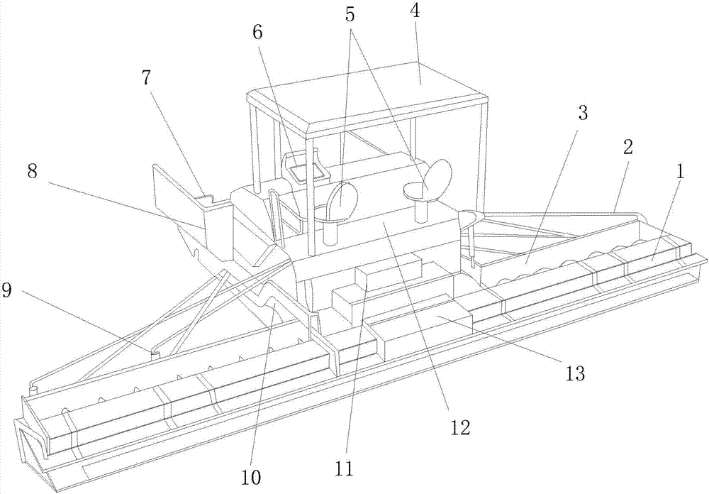
[0038] see Figure 1-Figure 5 , the present invention provides a quick asphalt paving and maintenance device based on municipal road engineering, its structure includes a paving mechanism 1, a control rod 2, a screed 3, a cover roof 4, a seat 5, a device operating platform 6, and a material pushing roller 7 , Hopper 8, connecting column 9, screw distributor 10, pedal 11, standing platform 12, middle connecting block 13.

[0039] The paving mechanism 1 is located at the front end of the covered ceiling 4, the paving mechanism 1 is mechanically connected to the device operating platform 6 through the control rod 2, and the screw distributor 10 is located at the bottom of the standing platform 12 and connected to the hopper 8 In communication, the other end of the screw distributor 10 communicates with the paving mechanism 1, the screed 3 is installed at the rear end of the paving mechanism 1, and the front end of the standing platform 12 is also fixed with a pedal 11, so A seat...

Embodiment 2

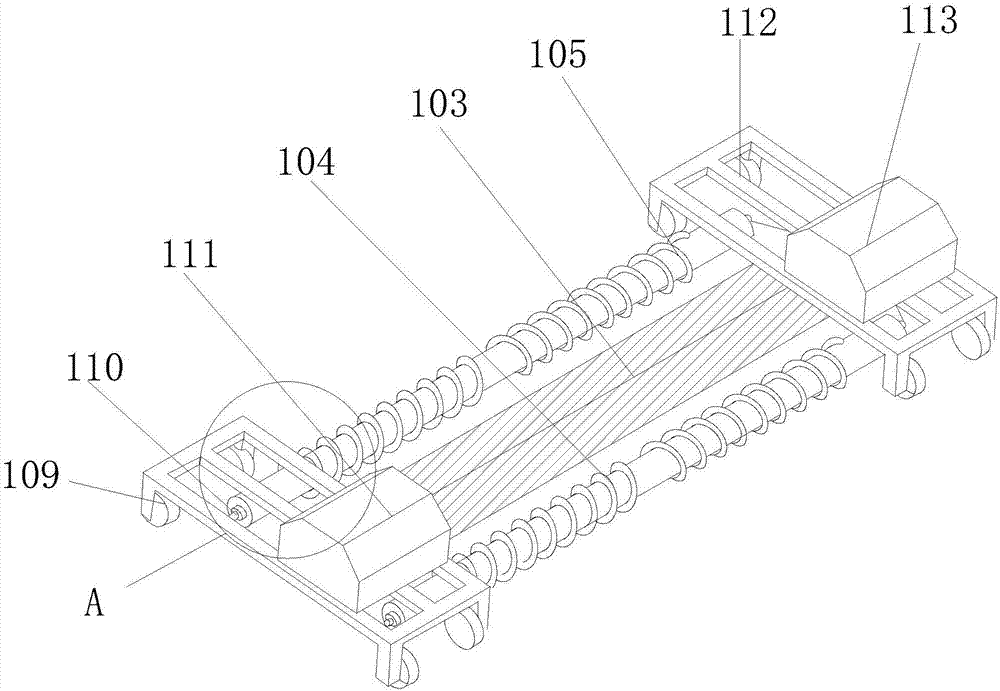
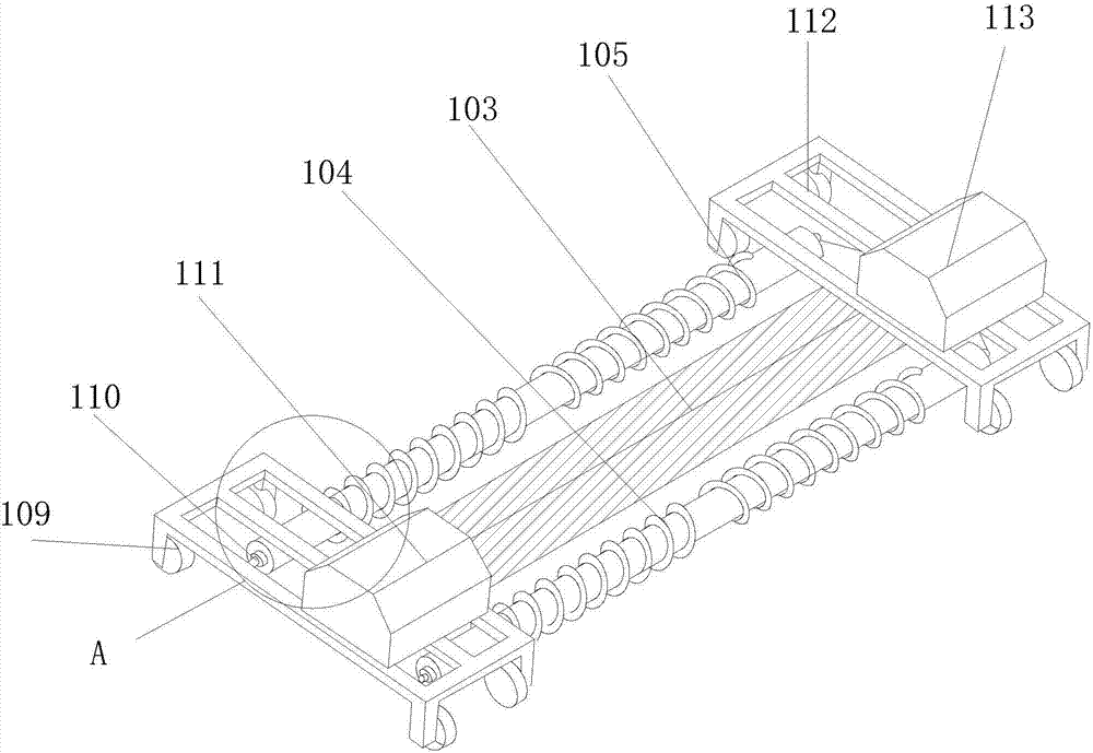
[0045] see Figure 1-Figure 9 , the left weighting mechanism 111 of the present invention and the right weighting mechanism 113 are all provided with rotating shaft connection hole 1111, left hanging wheel 1112, driven drive rod 1113, multi-faceted cam 1114, drive shaft 1115, right hanging wheel 1116, gravity plate 1117, Vibration plate 1118, first return spring 1119, right support rod 11110, bottom ring 11111, compaction beam 11112, telescopic rod 11113, left support rod 11114, second return spring 11115, fixed panel 11116, fixed nut 11117.

[0046] The left and right hanging wheels 1112 and the right hanging wheels 1116 are provided at the left and right ends of the fixed panel 11116, and the left hanging wheel 1112, the right hanging wheel and the fixed panel 11116 are fixedly connected by fixing nuts 11117, and the drive shaft 1115 The left end is provided with a rotating shaft connection hole 1111, and the drive shaft 1115 passes through the left hanging wheel 1112, the m...


PUM


Abstract

The invention discloses an asphalt rapid paving and maintenance device based on municipal road engineering. Distributor, pedal, standing platform, intermediate connecting block, the paving mechanism is located at the front end of the covered roof, the paving mechanism is mechanically connected with the device operating platform through the control rod, the screw distributor is located at the bottom of the standing platform and communicates with the hopper, the spiral The other end of the feeder is connected to the paving mechanism. The first screw rod and the second screw rod of the present invention are laid at the same time without secondary laying. After working for a long time, the current is unstable, which leads to the inability to maintain a uniform speed of paving, which affects the effect of asphalt road paving. The left weighting mechanism and the right weighting mechanism are added. The shaping effect of the road paved at both ends of the paving mechanism is the same as that of the middle position.

Description

technical field [0001] The invention relates to a rapid asphalt paving and maintenance device based on municipal road engineering, which belongs to the field of municipal engineering equipment. Background technique [0002] The rapid development of my country's urban economy has largely promoted the development of my country's road construction technology. Among them, asphalt concrete is the most common road type in my country's municipal road construction, and new technologies emerging in urban municipal roads have contributed to the development of municipal networks. With the rapid improvement of the construction level, asphalt concrete pavement has quickly become the main road type in the current municipal engineering due to its advantages of convenient construction and simple maintenance. However, asphalt roads also have some shortcomings of their own, such as easy deformation, low temperature resistance, etc. Especially in a metropolis like Shenzhen, the continuous deepen...

Claims


Application Information

Patent Timeline
IPC IPC(8): E01C19/48
CPCE01C19/486
Inventor 卢晓惠
Owner 卢晓惠
Learn More