
Low-temperature valve airtightness test device

A test device and air-tightness technology, which is applied in the direction of liquid-tightness measurement using liquid/vacuum degree, etc. It can solve the problems that the valve sealing performance cannot meet the process requirements, the valve sealing surface is not clean, and the thread of the valve body is easy to be damaged. , to achieve the effect of convenient and quick maintenance, reduced test cost and good sealing performance

Inactive Publication Date: 2015-01-28
江南工业集团有限公司
View PDF7 Cites 18 Cited by
  • Summary
  • Abstract
  • Description
  • Claims
  • Application Information

AI Technical Summary

Problems solved by technology

Although this traditional method can be used to test the air tightness of the valve, the work efficiency is low. Since most of the valve body is made of brass, the traditional connection method is easy to damage the valve body thread, and the copper shavings, copper Debris such as wire and raw tape used for sealing are more likely to enter the valve body, making the sealing surface of the valve unclean, resulting in the sealing performance of the valve not meeting the process requirements

Method used


Image

  • Low-temperature valve airtightness test device
  • Low-temperature valve airtightness test device
  • Low-temperature valve airtightness test device

Examples


Embodiment Construction

[0034] The best embodiment of the present invention will be further described below in conjunction with the accompanying drawings.

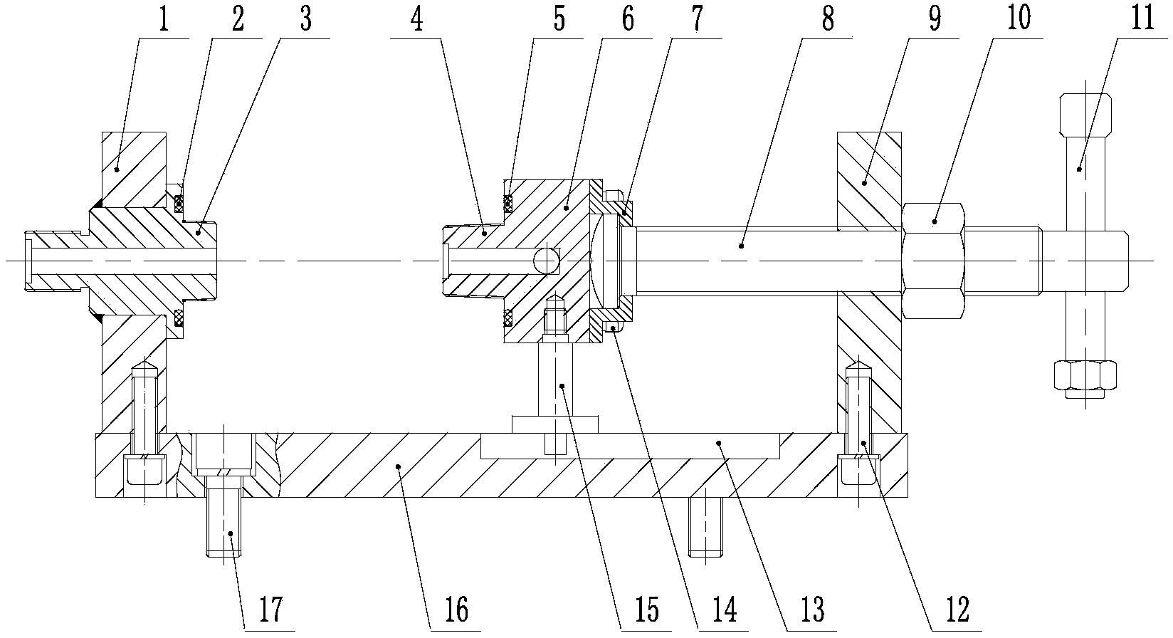
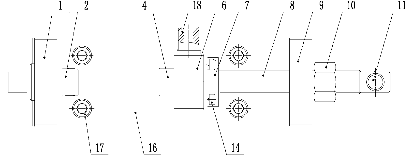
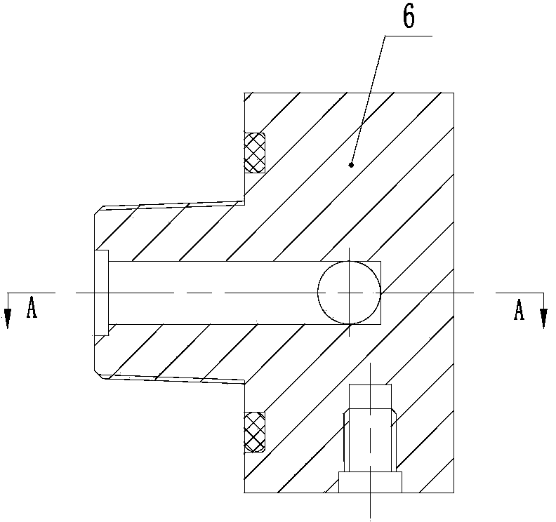
[0035] See attached figure 1 , 2 , A cryogenic valve air tightness test device, which includes left vertical plate 1, O-ring Ⅰ2, inlet joint 3, outlet joint 4, O-ring Ⅱ5, compression seat 6, end cover 7, mandrel 8 , Right vertical plate 9, lock nut 10, handle 11, connecting bolt I12, guide groove 13, connecting bolt II14, support shaft 15, bottom plate 16, connecting bolt III17, outlet joint 18.

[0036] See attached figure 1 , 2 , The left vertical plate 1 is provided with a smooth opening with the same outer diameter size as the inlet connector 3.

[0037] The right vertical plate 9 is provided with a threaded hole consistent with the top rod 8.

[0038] The upper end surface of the bottom plate 16 is provided with a longitudinal guide groove 13.

[0039] The left vertical plate 1 and the right vertical plate 9 are respectively fixed to the symmetrical ...


PUM


Abstract

The invention relates to a low-temperature valve airtightness test device, and belongs to the technical field of technological equipment. The test device is mainly and technologically characterized by comprising a left vertical plate, an O-shaped sealing ring I, an inlet joint, an outlet joint, an O-shaped sealing ring II, a pressing base, an end cover, an ejector rod, a right vertical plate, a lock nut, a handle, connecting bolts I, a guide groove, connecting bolts II, a supporting shaft, a bottom plate and connecting bolts III. The outlet joint, the left vertical plate and the right vertical plate are fixed to the two symmetrical ends of the upper end face of the bottom plate through the connecting bolts I, a connector with a guide conical surface is arranged at the right end of the inlet joint, the O-shaped sealing ring I is installed in a groove in the right end face of the inlet joint, a connector with a guide conical surface is arranged at the left end of the pressing base, the O-shaped sealing ring II is installed in a groove in the left end face of the pressing base, and the pressing base and the ejector rod are connected into a whole through the end cover. The low-temperature valve airtightness test device has the advantages of being compact and reasonable in structure, convenient and fast to use and maintain, capable of being reused, low in manufacturing cost and the like.

Description

Technical field [0001] The invention relates to a low-temperature valve air tightness test device, belonging to the technical field of process equipment, and is mainly suitable for testing the sealing performance of low-temperature insulated gas cylinder valves. Background technique [0002] The cryogenic valves used in cryogenic insulated gas cylinders have strict requirements on air tightness, especially when the storage medium is flammable and explosive materials. At present, there are various types of cryogenic valves in China, and their functions and structures are also different. The test device for detecting the air tightness requirements of the valve also needs to be equipped with different structures. In the background art, when testing the air tightness of cryogenic valves in China, almost always use a transitional threaded joint to connect between the tested valve and the external pipeline, and the threaded joint is used as an intermediate connection bridge. Although ...

Claims


Application Information

Patent Timeline
Patent Type & Authority Applications(China)
IPC IPC(8): G01M3/02
Inventor 杨巾莹王健李崇华熊雁鸣刘亮
Owner 江南工业集团有限公司
Learn More