Backlight module and display device

A backlight module and display device technology, applied in light guides, optics, optical components, etc., can solve problems such as low utilization rate of light sources, light decay of light sources affecting product display quality, etc.

Inactive Publication Date: 2015-01-28
BOE TECH GRP CO LTD
View PDF5 Cites 7 Cited by
  • Summary
  • Abstract
  • Description
  • Claims
  • Application Information

AI Technical Summary

Problems solved by technology

[0006] The technical problem to be solved by the present invention is to provide a backlight module and a display device to overcome defects such as low light source utilization rate in the prior art, which easily causes serious light decay of the light source and affects product display quality.

Method used


Image

  • Backlight module and display device
  • Backlight module and display device
  • Backlight module and display device

Examples


Embodiment 1

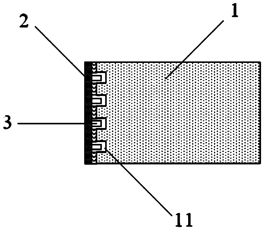
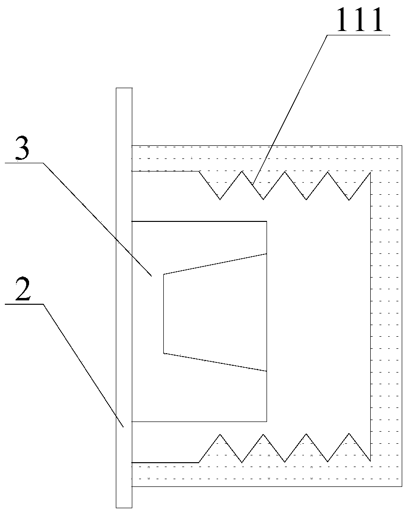
[0031] Such as Figure 1~4 As shown, the present invention provides a backlight module, which includes:

[0032] The light guide plate 1 and the PCB substrate 2 located on both sides of the light guide plate 1, the PCB substrate 2 is provided with several light source devices 3;

[0033] Two sides of the light guide plate 1 facing the PCB substrate 2 are provided with several grooves 11 for accommodating the light source device 3; two opposite inner walls of the groove 11 are provided with several protrusions 111.

[0034] The protrusion 111 is made by the light guide plate 1 and is directly formed on the inner wall of the groove 11 . That is, when the groove 11 is formed on the light guide plate 1 , the pattern of the protrusion 111 is also formed.

[0035] In this embodiment, the two sides of the light guide plate are arranged in a groove structure, which can better accommodate the light source device, save the occupied area of ​​the light source device to the greatest ext...

Embodiment 2

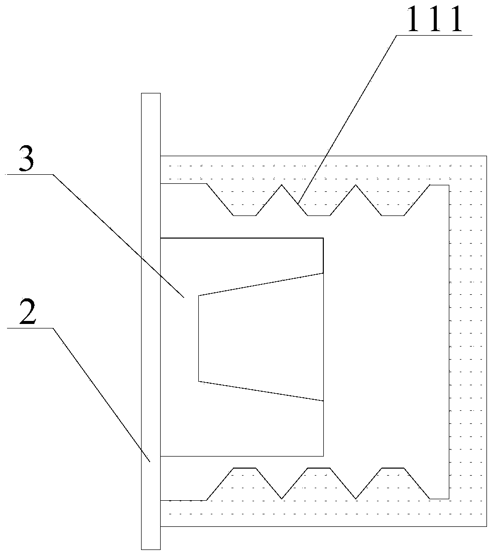
[0045] Such as Figure 5 As shown, the difference between the backlight module provided in this embodiment and the first embodiment is that the protrusion 111 is made of a lens film, and the lens film is pasted on two opposite inner walls of the groove 11 . That is, it is enough to form the groove 11 on the light guide plate 1 , and the lens film is pasted on the two opposite inner walls of the groove by sticking the lens film.

[0046] Similarly, the lens film can also be polygonal or arc-shaped, the polygon can be triangle and quadrangle, and the quadrangle can be rectangle, trapezoid or other irregular quadrilateral;

[0047] The arc can be a semicircle, a semi-ellipse, or other irregular arcs.

[0048] The lens film can use different shapes as protrusions of different shapes to further reflect more light and improve the effective use of light.

[0049] On the other hand, the present invention also provides a display device, comprising the above-mentioned backlight module...


PUM


Abstract

The invention relates to the field of display technology, particularly to a backlight module and a display device. The backlight module comprises a light guide plate and PCB (printed circuit board) substrates on both sides of the light guide plate; one side of each PCB substrate, which faces towards the light guide plate, is provided with a plurality of light source devices; one side of the light guide plate, which faces towards the PCB substrates, is provided with a plurality of slots for accommodating the light source devices; the two opposite inner walls of every slot are provided with a plurality of protrusions. According to the backlight module and the display device, one side of the light guide plate is provided with the plurality of slots for accommodating the light source devices, and the two opposite inner walls of every groove are provided with the plurality of protrusions, so that light emitted from the side walls of the light source devices can be utilized to the maximum degree, and the light energy utilization rate can be improved, and further achieving required light intensity through fewer light source devices; energy conservation can be achieved, meanwhile, the heat dissipating burden of the light source devices can be effectively reduced, and further the internal temperature of the backlight module can be reduced, and the service life of products can be prolonged.

Description

technical field [0001] The invention relates to the field of display technology, in particular to a backlight module and a display device. Background technique [0002] At present, liquid crystal displays mostly use a backlight module to provide power to the display panel, and a light guide plate is used in the backlight module to evenly disperse the light emitted by the light source. [0003] The existing light guide plate is plate-shaped, and its light loss is about 30%, and light leakage is prone to occur on the side of the light guide plate, and additional black tape needs to be added to cover the light leakage area, resulting in a low light output rate and affecting the display quality of the product . [0004] In addition, the plate-shaped light guide plate does not have a corresponding position for accommodating light source devices, which limits the narrow frame configuration of the product. Contents of the invention [0005] (1) Technical problems to be solved ...

Claims


Application Information

Patent Timeline
Patent Type & Authority Applications(China)
IPC IPC(8): G02F1/13357G02F1/1335
CPCG02B6/0016G02B6/0021G02B6/0073G02F1/133603G02F1/133615G02B6/0068G02B6/003G02B6/0055
Inventor 朱琳武延兵王浩
Owner BOE TECH GRP CO LTD
Why Eureka
Try Eureka